Data table structure – Rockwell Automation 1203 Serial Communications Module Series B User Manual
Page 37
4–3
Configuring and Interfacing
1203–5.5 September 1995
Data Table Structure
The Serial Communications Module provides the following data
table structures for DF1 and DH–485.
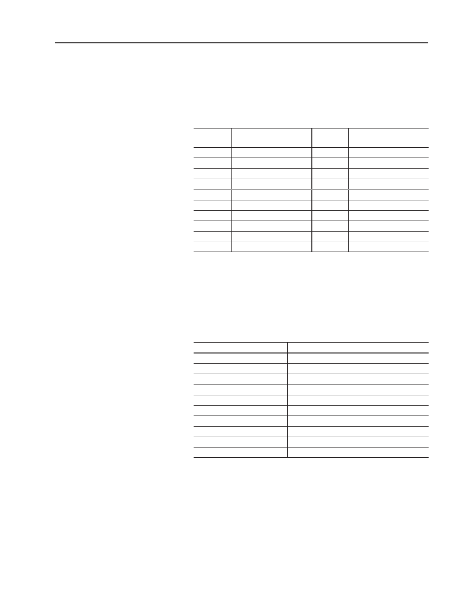
The following table is the drive control table (binary file).
File
Address
Description
File
Address
Description
B3:0
Logic Command
B3:10
Logic Status
B3:1
Reference
B3:11
Feedback
B3:2
Datalink A1 In (to Drive)
B3:12
Datalink A1 Out (from Drive)
B3:3
Datalink A2 In (to Drive)
B3:13
Datalink A2 Out (from Drive)
B3:4
Datalink B1 In (to Drive)
B3:14
Datalink B1 Out (from Drive)
B3:5
Datalink B2 In (to Drive)
B3:15
Datalink B2 Out (from Drive)
B3:6
Datalink C1 In (to Drive)
B3:16
Datalink C1 Out (from Drive)
B3:7
Datalink C2 In (to Drive)
B3:17
Datalink C2 Out (from Drive)
B3:8
Datalink D1 In (to Drive)
B3:18
Datalink D1 Out (from Drive)
B3:9
Datalink D2 In (to Drive)
B3:19
Datalink D2 Out (from Drive)
Note: If you write to B3:0 through B3:9, you will write data to the
drive. If you read from B3:0 through B3:9, you will return the data
being currently sent to the drive. If you read from B3:10 through
B3:19, you will read data from the drive. If you write to B3:10
through B3:19, you will receive an error.
The following table is the drive control table (integer file).
File Address
Description
N41:0
Logic Command/Status
N41:1
Reference/Feedback
N41:2
Datalink A1
N41:3
Datalink A2
N41:4
Datalink B1
N41:5
Datalink B2
N41:6
Datalink C1
N41:7
Datalink C2
N41:8
Datalink D1
N41:9
Datalink D2
Note: If you write to any location in N41, you will write data to the
drive. If you read from any location in N41, you will read data from
the drive.
"
"