Functional diagram, Front side and user elements, Ab c d e – Rockwell Automation 1606-XLE240F-3 Power Supply Reference Manual User Manual
Page 9
All parameters are specified at 24V, 2.5A, 230Vac input, 25ªC ambient and after a 5 minutes run-in time unless noted otherwise.
Rockwell Automation Publication 1606-RM031A-EN-P — April 2014
9
Bulletin 1606 Switched Mode Power Supplies
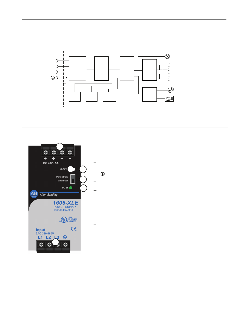
9. Functional Diagram
Fig. 9-1 Functional diagram
+
+
-
-
V
OUT
Output
Over-
Voltage
Protection
PFC
Inductor
Inrush
Limiter
Transient
Filter
Input Fuses
Input Filter
Input
Rectifier
Output
Voltage
Regulator
Power
Converter
Output
Filter
Output
Power
Manager
Temper-
ature
Shut-
down
DC-ok
LED
L2
L3
L1
Single /
Parallel
10. Front Side and User Elements
A Output Terminals
Screw terminals, dual terminals per pole
+ Positive output
- Negative (return) output
B Input
Terminals
Screw
terminals
L1, L2, L3 Phase input
PE (Protective Earth) input
C Output
voltage
potentiometer
Open the flap to set the output voltage. Factory set: 48.0V
D “Parallel Use” “Single Use” selector
Set jumper to “Parallel Use” when power supplies are connected in
parallel to increase the output power. In order to achieve a sharing of
the load current between the individual power supplies, the “parallel
use” regulates the output voltage in such a manner that the voltage at
no load is approx. 5% higher than at nominal load. See also Fig. 6-2.
A missing jumper is equal to a “Single Use” mode.
Factory setting is “Single Use” mode.
E DC-OK LED (green)
On when the voltage on the output terminals is > 36V
A
B
C
D
E
Fig. 10-1 Front side