Charging batteries, Output circuit breakers – Rockwell Automation 1606-XLE240F-3 Power Supply Reference Manual User Manual
Page 18
All parameters are specified at 24V, 2.5A, 230Vac input, 25ªC ambient and after a 5 minutes run-in time unless noted otherwise.
18
Rockwell Automation Publication 1606-RM031A-EN-P — April 2014
Bulletin 1606 Switched Mode Power Supplies
22.3. Charging Batteries
The power supply can be used to charge lead-acid or maintenance free batteries. (4x 12V batteries in series)
Instructions for charging batteries:
a)
Set jumper on the front of the unit into “Parallel Use”
b)
Set output voltage (measured at no load and at the battery end of the cable) very precisely to the end-of-charge
voltage.
End-of-charge voltage
55.6V
55V
54.3V
53.6V
Battery temperature
10°C
20°C
30°C
40°C
c)
Use a 10A circuit breaker (or blocking diode) between the power supply and the battery.
d)
Ensure that the output current of the power supply is below the allowed charging current of the battery.
e)
Use only matched batteries when putting 12V types in series.
f)
The return current to the power supply (battery discharge current) is typ. 4.4mA when the power supply is
switched off (except in case a blocking diode is utilized).
22.4. Output Circuit Breakers
Standard miniature circuit breakers (MCBs or UL1077 circuit breakers) are without a doubt one of the most efficient
and economical ways to open circuits on faulty branches. Most of these breakers may also be used on 48V branches.
MCBs are designed to protect wires and circuits. If the ampere value and the characteristics of the MCB are adapted to
the wire size that is used, the wiring is considered as thermally safe regardless of whether the MCB opens or not.
To avoid voltage dips and under-voltage situations in adjacent 48V branches which are supplied by the same source, a
fast (magnetic) tripping of the MCB is desired. A quick shutdown within 10ms is necessary corresponding roughly to
the ride-through time of PLCs. This requires power supplies with high current reserves and large output capacitors.
Furthermore, the impedance of the faulty branch must be sufficiently small in order for the current to actually flow.
The best current reserve in the power supply does not help if Ohm’s law does not permit current flow. The following
table has typical test results showing which B- and C-Characteristic MCBs magnetically trip depending on the wire cross
section and wire length.
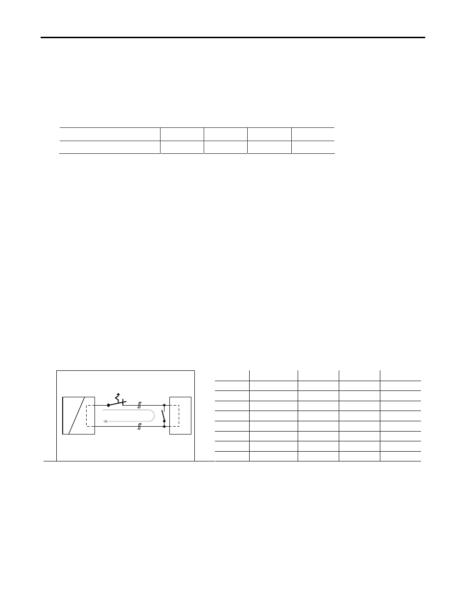
Fig. 22-3 Test circuit
Maximal wire length for a magnetic (fast) tripping
*)
:
0.75mm² 1.0mm² 1.5mm² 2.5mm²
C-2A 52m 70m
94m
148m
C-3A 33m 42m
64m
97m
C-4A 19m 23m
33m
48m
C-6A 8m 9m
13m
22m
C-8A - - - -
C-10A -
- - -
B-6A 18m 22m
33m
46m
MCB
Power
Supply
AC
DC
+
-
Load
+
-
B-10A 4m 5m 10m 13m
Wire length
S1...... Fault Simulation Switch
S1
*) Remember to take into account twice the distance to the load (or cable length) when calculating the total wire length (+ and – wire).