Rockwell Automation 1492-AIFM4C-F_AIFM4I-F-5 4 Channel Fusible Analog Input Interface Modules User Manual
Page 4
PN-104510
DIR 40063-331 (Version 08)
(4)
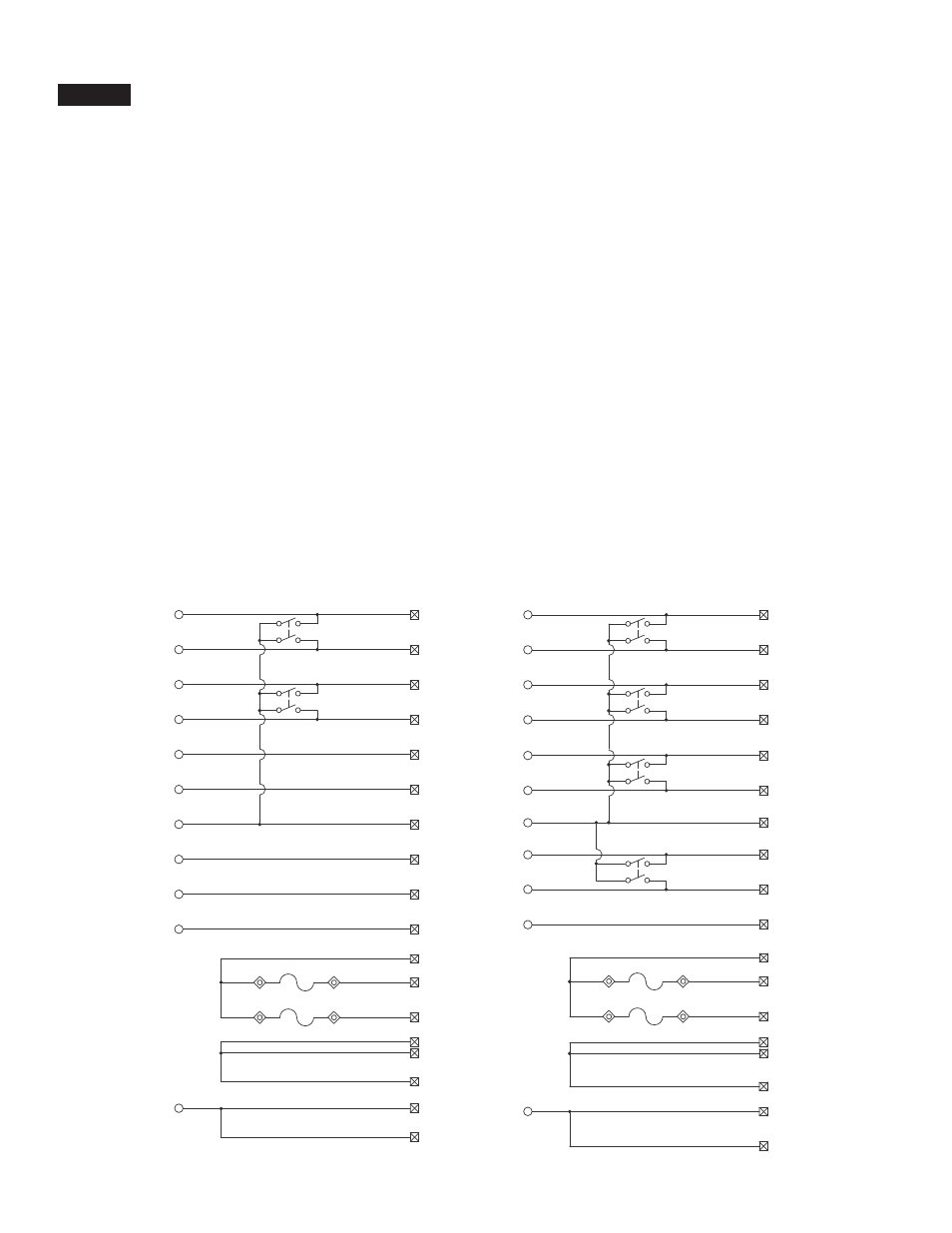
Pinout
Brochage
Anschlußbelegung
Disposizione
dei piedini
Esquema de pins
I/O Wiring Data
1492-AIFM4C-F-5
B1
8
A8
B2
A5
B3
B4
B5
B6
B7
B8
B9
B10
B11
A2
A1
B12
15
14
13
12
11
2
10
SH
9
1
TP1
TP2
TP3
TP4
A12
A9
.
.
.
.
.
.
.
.
B1
8
A8
B2
A5
B3
B4
B7
B5
B6
B8
B9
B10
B11
A4
A1
B12
15
14
13
2
12
11
10
SH
9
1
TP1
TP2
TP7
TP8
A12
A9
..
..
.
..
..
.
..
..
.
1492-AIFM4I-F-5
NOTICE
Wiring information for your I/O module, AIFM module and cable (e.g. wiring diagram and pinouts)are available online at www.rockwellautomation.com/en/e-tools.
To obtain information follow this procedure.
1) In the Catalog Number BOX at the above online site type in the catalog number of the IFM, AIFM, etc. module you are using and click on Submit.
2) At the next screen displayed, click on the Modify key (lower left of screen).
3) Click on the areas that indicate NO SELECTION and enter your specific configuration information (e.g. I/O platform, I/O MODULE, ETC.).
NOTE: To obtain the wiring diagram, you must select th Pre-Wired Cable Connector selection.
4) Configure your 1492 cable by filing in the NO SELECTION areas.
5) Click on the ACCEPT key for the configured 1492 cable. At the next screen click on ACCEPT for the 1492 module.
6) The next screen (Configuration Results) displays the results of your specific configuration. The "supplementary Documents" column contains I/O wiring information
for the configuration (e.g. I/O Wiring Diagrams).