1+1 redundancy up to 20a, N+1 redundancy, example with 60a – Rockwell Automation 1606-XLSRED40 Power Supply Reference Manual User Manual
Page 16
All parameters are specified at 24V, 40A output current, 26°C ambient and after a 5 minutes run-in time, unless noted otherwise.
16
Rockwell Automation Publication 1606-RM010A-EN-P — February 2014
Bulletin 1606 Switched Mode Power Supplies
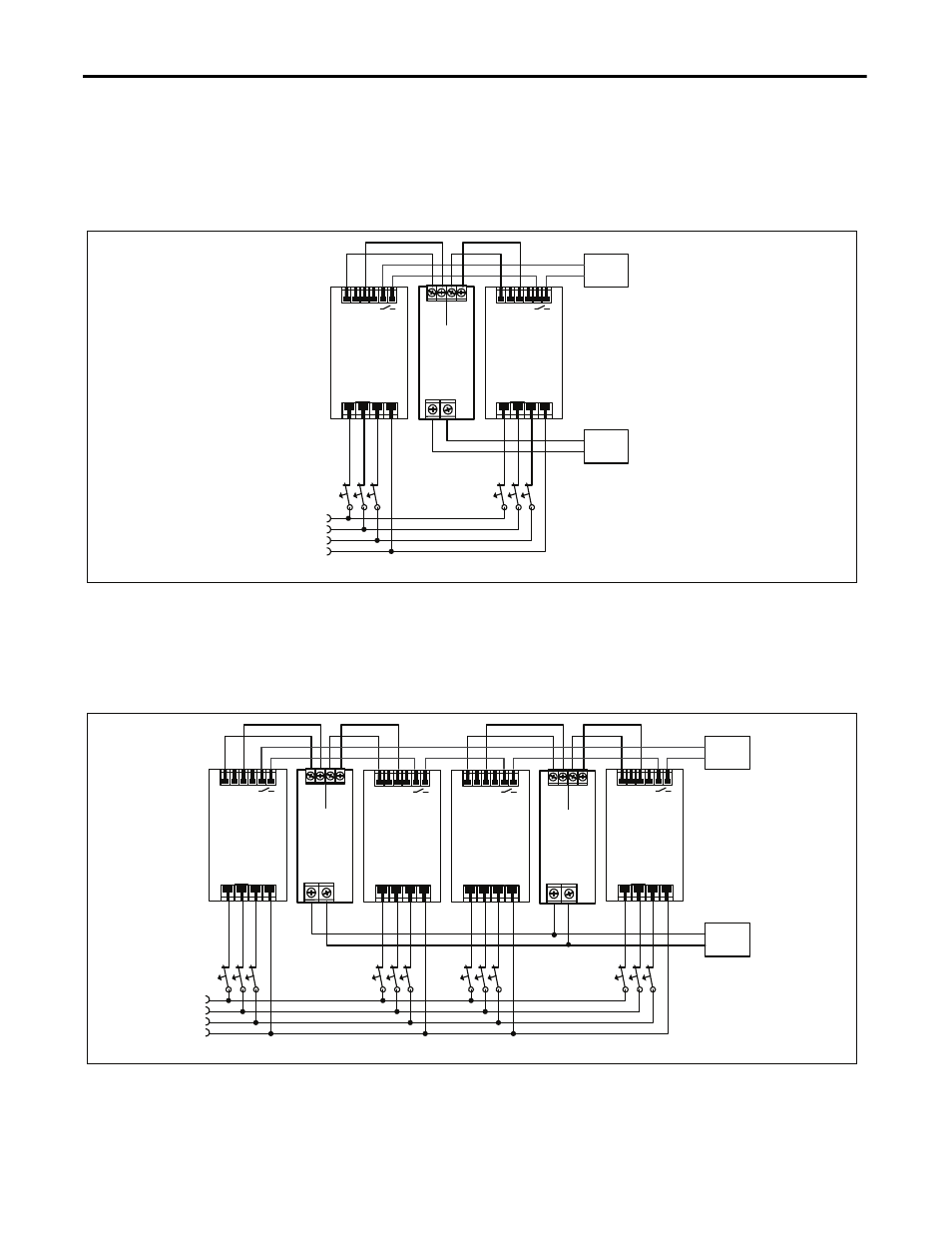
17.4. 1+1 Redundancy up to 20A
1+1 Redundancy up to 20A requires two 20A power supplies and one 1606-XLSRED40 redundancy module.
Fig. 17-1 Wiring diagram, 1+1 Redundancy, 20A output current
L1
L2
PE
L3
20A
Load
Failure
Monitor
I
I
I
I
I
I
L1 L2 L3 PE
+ +
- -
Power
Supply
24V,20A
DC-
OK
L1 L2 L3 PE
+ +
- -
Power
Supply
24V,20A
DC-
OK
1606-
XLSRED40
Redundancy
Module
Output
Input
1
Input
2
+
-
+
-
+
-
Note: Use separate mains systems for each power supply whenever possible.
17.5. N+1 Redundancy, Example with 60A
N+1 Redundancy up to 60A requires four 20A power supplies and two 1606-XLSRED40 redundancy modules.
Fig. 17-2 Wiring diagram, n+1 Redundancy, 60A output current
60A
Load
Failure
Monitor
I
I
I
I
I
I
I
I
I
L1
L2
PE
L3
L1 L2 L3 PE
+ +
- -
Power
Supply
24V,20A
DC-
OK
L1 L2 L3 PE
+ +
- -
Power
Supply
24V,20A
DC-
OK
1606-
XLSRED40
Redundancy
Module
Output
Input
1
Input
2
+
-
+
-
+
-
L1 L2 L3 PE
+ +
- -
Power
Supply
24V,20A
DC-
OK
L1 L2 L3 PE
+ +
- -
Power
Supply
24V,20A
DC-
OK
1606-
XLSRED40
Redundancy
Module
Output
Input
1
Input
2
+
-
+
-
+
-
I
I
I
Note: Use separate mains systems for each power supply whenever possible.