V. wiring diagrams (cont’d), Cable”b, Cable”a – Rockwell Automation 1492-CM1771-LA003 Analog & Digital I/O Conversion Module User Manual
Page 7
(7)
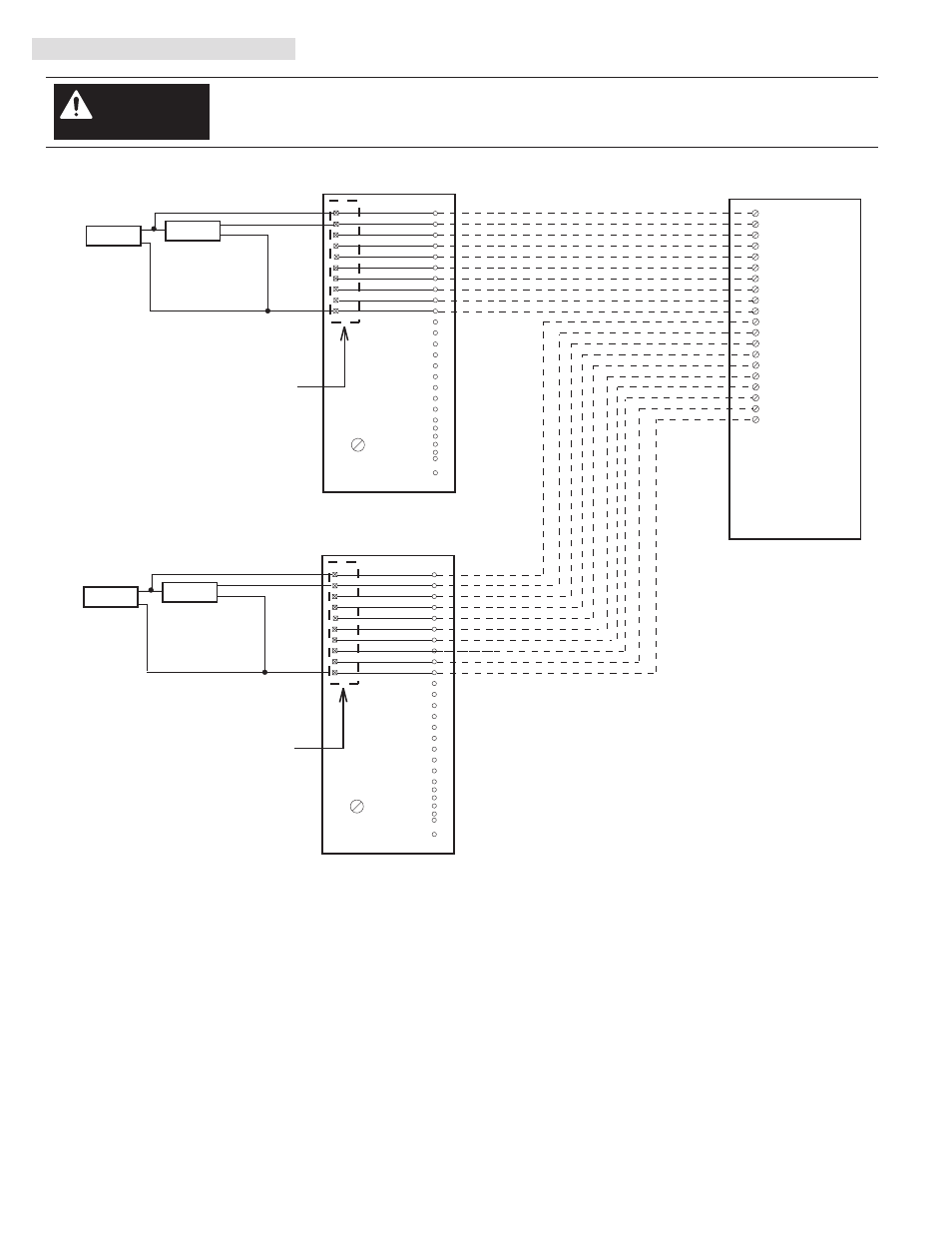
V. Wiring Diagrams (Cont’d)
There are several key application considerations and system specifications (bottom of drawing) when
using these components (conversion module, cable and input module). Read and understand these
considerations before installation.
WARNING
1771-WC Swing Arm
From 1771-OG
1771-WC Swing Arm
From 1771-OG
Conversion Module
1492-CM1771-LA003
Conversion Module
1492-CM1771-LA003
Cable
1492-C005005XS
1756-OG16
Conversion: 1771-OG (2) to 1756-OG16 (1)
Output
Device
13
25
24
23
22
21
19
18
17
16
1
2
SH
Output 0
+ DC
10
OUT-0
OUT-1
1
OUT-2
2
3
4
5
6
7
9
8
Red/White
Green/Black/White
Black/White/Red
White/Black/Red
Orange/Green
Red/Black/White
Orange/Red
Blue/Red
+
-
A
3
4
5
6
7
B
0
1
2
Common
Output 1
Output 2
Output 3
Output 4
Output 5
Output 6
Output 7
3
4
5
6
7
8
9
10
11
12
14
15
20
OUT-3
OUT-4
OUT-5
OUT-6
OUT-7
+ DC -0
- DC -0
20
OUT-8
OUT-9
OUT-10
OUT-11
OUT-12
OUT-13
OUT-14
OUT-15
+ DC -1
- DC -1
13
25
24
23
22
21
19
18
17
16
1
2
SH
Red/White
Green/Black/White
Black/White/Red
White/Black/Red
Orange/Green
Red/Black/White
Orange/Red
Blue/Red
A
3
4
5
6
7
B
0
1
2
3
4
5
6
7
8
9
10
11
12
14
15
20
Output 8
+ DC
Common
Output 9
Output 10
Output 11
Output 12
Output 13
Output 14
Output 15
11
12
13
14
15
16
17
18
19
Black/Red
White/Red
Black/Red
White/Red
CABLE”B”
+
-
5V DC
SUPPLY
Output
Device
+
-
+
-
5V DC
SUPPLY
Conversion Module Installation and Application Considerations
This Bul. 1492 cable consists of 2 separate cables (cable “A” and cable “B”) wired to one 1756-OG16 RTB. Each cable can be either 0.5M or
1.0M (005=0.5M, 010=1.0M). Ensure that cable A and cable B are connected to the correct module in the conversion.
The input delay times for the 1771-OG module versus the 1756-OG16 module are as follows:
1771-OG
1756-OG16 w/ 1492-C005005XS
a) Off-to-On Delay
1ms (+/-10ms)
45ms max (plus selectable filter)
b) On-to-Off Delay
1ms (+/-10ms)
145ms max (plus selectable filter)
The 1771-OG module is rated 5V DC TTL INPUT MODULE. The 1756-OG16 module is rated 5V DC TTL INPUT MODULE only.
Refer to your 1771-OG and 1756-OG16 Installation and User Manuals for additional information concerning comparisons of module wiring,
features and configuration details.
[Reference Doc: 41171-028 (Version 00)]
PN-114289
DIR 10000060100 (Version 01)
Publication 1492-IN047B-EN-E
CABLE”A”