V. wiring diagrams – Rockwell Automation 1492-CM1771-LA003 Analog & Digital I/O Conversion Module User Manual
Page 4
(4)
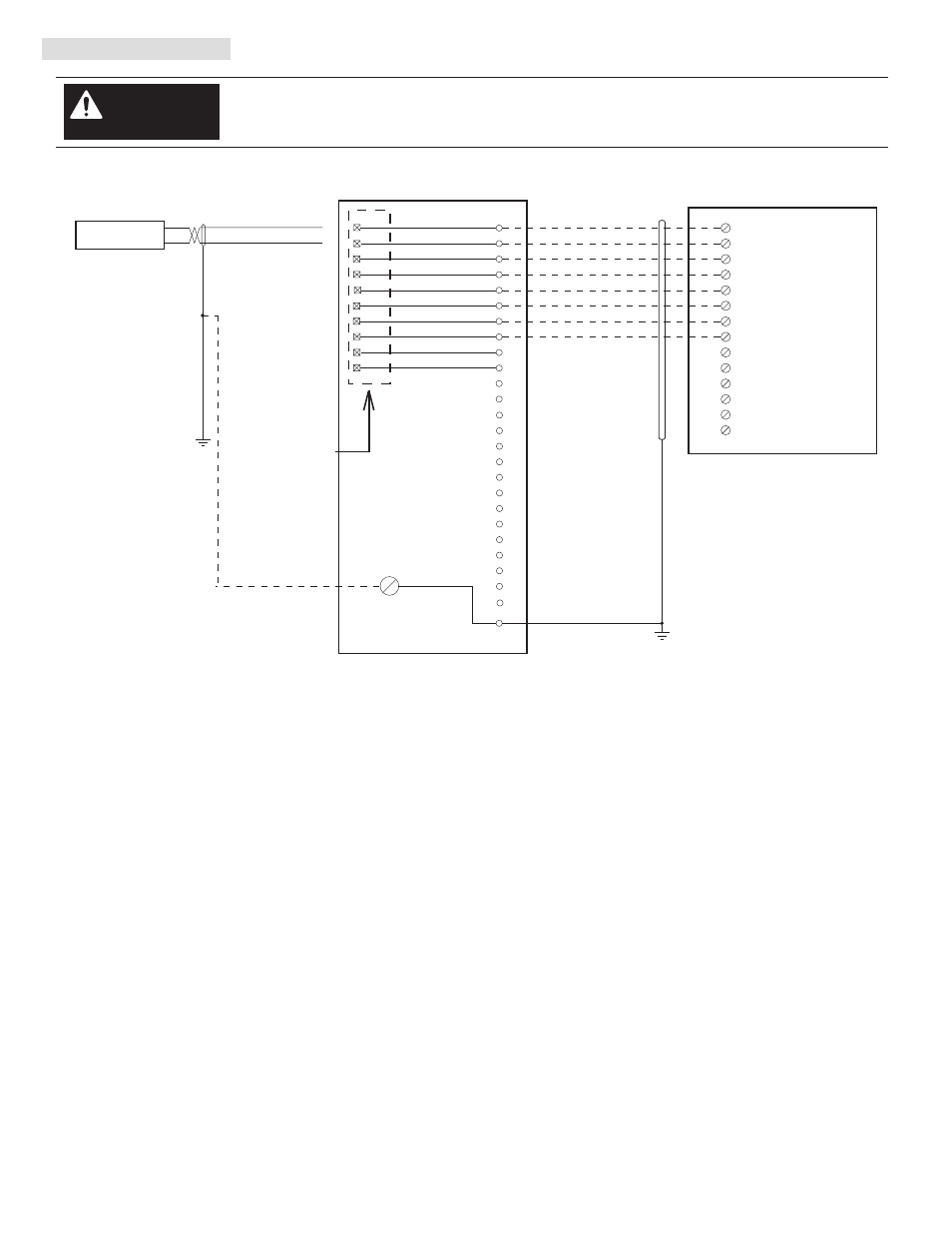
V. Wiring Diagrams
There are several key application considerations and system specifications (bottom of drawing) when
using these components (conversion module, cable and input module). Read and understand these
considerations before installation.
WARNING
Conversion: 1771-OFE1 to 1756 -OF6VI
Conversion Module Installation and Application Considerations
This Bul. 1492 cable consists of a cable wired to one 1756-OF6VI RTB. Recommended cable lengths of 0.5M or 1.0M (005=0.5M, 010=1.0M).
See table 2 for other lengths.
SHIELD GROUNDING: In some installations, the field wiring shield was grounded on the 1771 chassis. If this was the case, the installer must
remove these shield connections from the 1771 chassis and they can be connected to the grounding stud on the 1492-CM1771-LA003 module.
The pre-wired cable used between the 1492-CM1771-LA003 module and the 1756-OF6VI [1492-CONACAB005E] provides a shield ground lug to
ground the shield at the 1756 ControlLogix chassis, this must be connected. Do NOT connect this ground lug to the conversion module grounding
stud.
The 1771-OFE1 analog output range was configured by jumpers, the output range for the 1756-OF6VI is software configured. Please ensure
the correct output range is configured in the 1756-OF6VI.
Refer to your 1771-OFE1 and 1756-OF6VI Installation and User Manuals for additional information concerning comparisons of module wiring,
features and configuration details.
[Reference Doc: 41170-949 (Version 02)]
1771-WC Swing Arm
From 1771-OFE1
Conversion Module
1492-CM1771-LA003
Cable
1492-CONACAB005E
1756-OF6VI
PN-114289
DIR 10000060100 (Version 01)
Publication 1492-IN047B-EN-E
13
25
24
23
22
21
19
18
17
16
1
2
SH
Channel 1 Out +
Not Used
1
OUT-0
RTN-0
5
OUT-1
2
RTN-1
6
OUT-2
7
RTN-2
11
OUT-3
8
RTN-3
12
RTN-4
19
OUT-4
15
14
13
Red/White
Green/Black/White
Black/White/Red
White/Black/Red
Orange/Green
Red/Black/White
Orange/Red
Not Used
Not Used
Not Used
Not Used
20
16
Blue/Red
Voltage
Load
+
-
A
3
4
5
6
7
B
0
1
2
Not Used
Channel 1 Out -
Channel 2 Out +
Channel 2 Out -
Channel 3 Out +
Channel 3 Out -
Channel 4 Out +
Channel 4 Out -
3
4
5
6
7
8
9
10
11
12
14
15
20