Rockwell Automation 1321-M Common Mode Chokes User Manual
Page 7
1321-M Common Mode Chokes
7
M180 Mounting and Wiring
To install the choke assembly, follow these steps
1. Remove all power connected to the system.
2. Mount the M180 Choke Assembly on a metal surface near the
bottom of the drive cabinet using 1/4-20 hardware. Leave
sufficient clearance between the choke assembly and the drive
terminals to allow access to the terminals and provide proper
bend radius for the leads.
3. Terminate the motor leads at the T1/U, T2/V, T3/W connections
on the motor as shown in the figure on the following page. An
optional terminal strip may be used between the choke assembly
and the motor if desired. A properly sized ground conductor from
the motor frame is also required. The ground conductor is routed
around (not through) the choke and connected to the Drive Power
Earth @ TB1-PE.
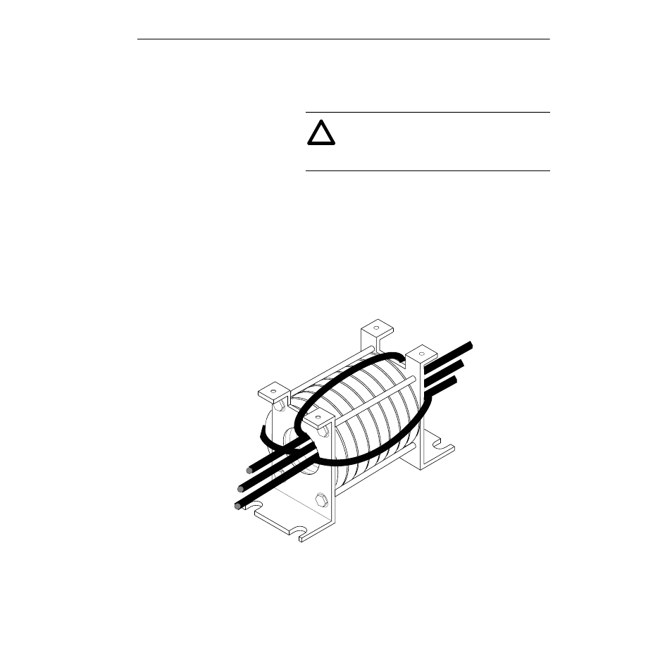
4. If possible, wrap each lead once around the core before
terminating at the drive terminals. If the motor lead gauge is too
thick to allow one wrap, run the leads straight thru the choke
assembly to drive terminals TB-1, U (T1), V (T2) and W (T3) as
shown in the following figure. Running the motor leads straight
thru the core, will diminish the effectiveness of the installation.
!
ATTENTION: Electric shock can cause injury or
death. Remove all power before working with this
product. Verify that the voltage on the bus capacitors
has discharged. The voltage must be zero.
From T1 (U)
From T3 (W)
From T2 (V)
To Motor U (T1)
To Motor V (T2)
To Motor W (T3)