M009 mounting and wiring – Rockwell Automation 1321-M Common Mode Chokes User Manual
Page 4
4
1321-M Common Mode Chokes
M009 Mounting and Wiring
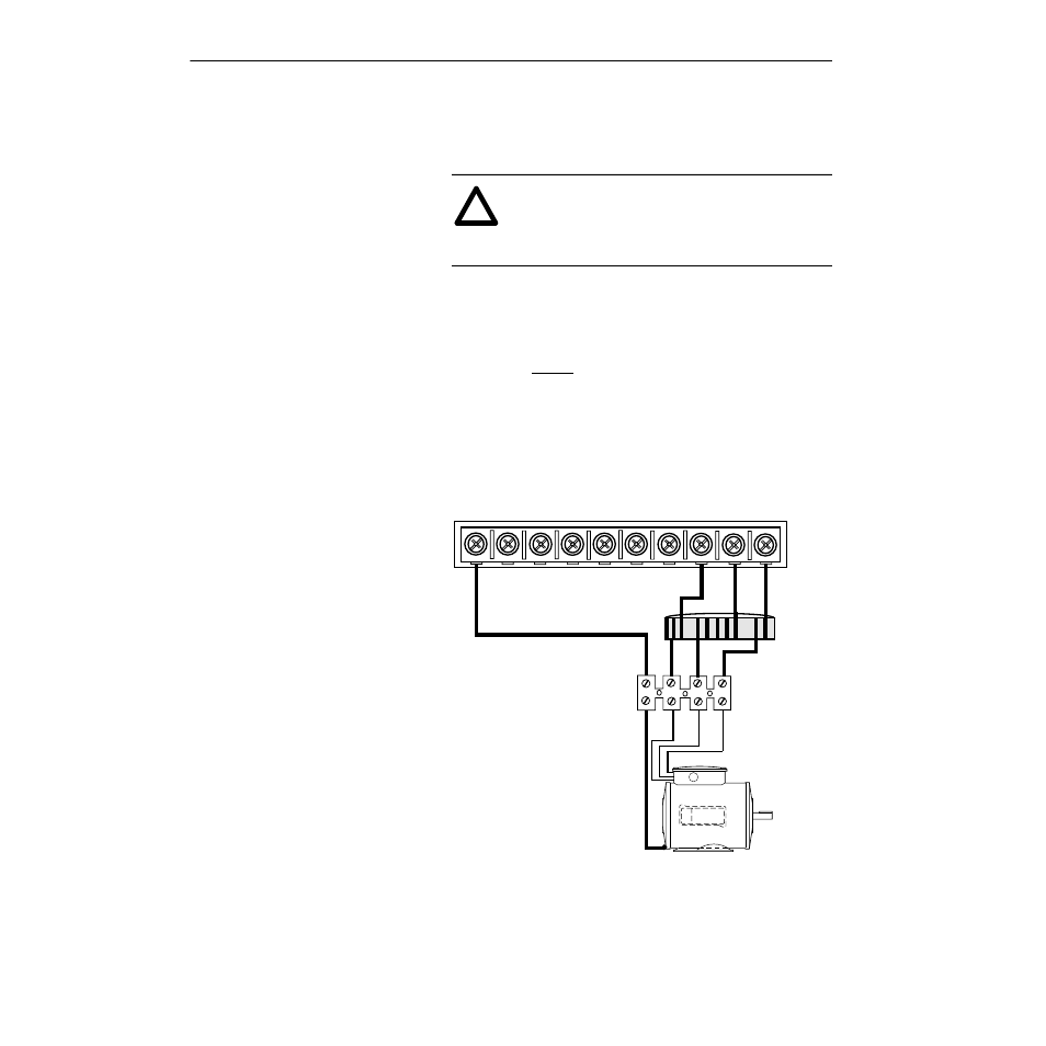
To install the choke assembly, follow these steps:
1. Remove all power connected to the system.
2. A 4 position terminal strip with preinstalled TB leads is included
with M009. Install leads from the terminal strip to TB1 (T3/W),
(T2/V) and (T1/U) of your drive. Make certain to leave at least 2
inches (50 millimeters) clearance between the choke assembly
and the drive terminals. Run the green 12 AWG lead from the
terminal strip outside the choke assembly to the PE connection on
the drive TB1 as shown in the following figure.
3. Run motor leads from the terminal strip to the T1/U,T2/V,T3/W
terminals on the motor as shown in the following figure. Run a 12
AWG ground lead from the terminal block to the ground point on
the motor frame.
4. When all wiring is completed, tie wrap the choke assembly to the
cabinet sheet metal or another suitable location to provide support
for the assembly. If the terminal strip supplied with the choke is to
be panel mounted, an insulation sheet must be used between the
terminal strip and the sheet metal.
!
ATTENTION: Electric shock can cause injury or
death. Remove all power before working with this
product. Verify that the voltage on the bus capacitors
has discharged. The voltage must be zero.
PE
Choke Assembly
1321 - M009
TB4
TB3
TB2
Motor
Frame
Ground
TB1
PE
DC+ DC-
R
(L1) (L2)
S
T
(L3)
U
V
(T1) (T2) (T3)
W
Terminal Strip
(Supplied With
Choke)
PE
GRD
U
V
W
T1
T2
T3
TB-1