Installation – Rockwell Automation 1321-M Common Mode Chokes User Manual
Page 3
1321-M Common Mode Chokes
3
Installation
All choke assemblies should be mounted as close to the bottom of the
drive as possible while leaving sufficient distance between the choke
assembly and the drive unit to provide clearance for cables and leads
to be installed at the drive. All choke assemblies with the exception of
the M001 and M009 are supplied with mounting brackets. Mounting
dimensions for each assembly are provided at the back of this
publication. It is recommended that M001 and M009 assemblies be
tie wrapped to a solid object such as cabinet sheet metal or brackets
when wiring is completed.
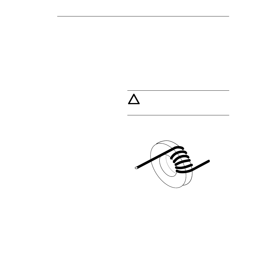
M001 Mounting and Wiring
To install the choke assembly, follow these steps:
1. Remove all power connected to the system.
2. Wrap the communication cable thru the choke assembly five
times as shown in the following figure. If the wire gauge is too
large to allow 5 wraps, you may use fewer wraps but this will
diminish the effectiveness of the installation.
3. Leave enough cable between the choke assembly and the drive to
allow the communication cable suitable clearance to be
terminated at the drive and for the choke assembly to be mounted
near the bottom of the drive cabinet. When all wiring is
completed, zip tie the choke assembly to the cabinet sheet metal
or another suitable location to provide support for the assembly.
!
ATTENTION: Electric shock can cause injury or
death. Remove all power before working with this
product. Verify that the voltage on the bus capacitors
has discharged. The voltage must be zero.
From
Communication
Device
Comm
Cable
To Drive