Calibration, Specifications – Rockwell Automation 1414-IPZxxxxx_CPZxxxxx_CPDxxxxx Differential Air Pressure Transmitter User Manual
Page 9
Differential Air-pressure Transmitter 9
Publication 1414-IN011B-EN-P - July 2010
Calibration
All pressure ranges are factory calibrated and no calibration is necessary. You may adjust the zero
point if desired when changing ranges for example.
1. Allow the product to warm-up for 10 minutes (one hour is best) before you make a zero
adjustment.
2. With both ports open to the ambient pressure, press and hold the auto-zero button for at
least three seconds.
3. Release the auto-zero button after at least three seconds and the device will calculate and
store the new zero point.
Specifications
TIP
Generally, we do not recommended that the span calibration be performed in
the field unless a high quality calibrator with low differential pressure ranges is
available and the temperature of the sensor can be maintained. Contact the
factory for information on this type of calibration.
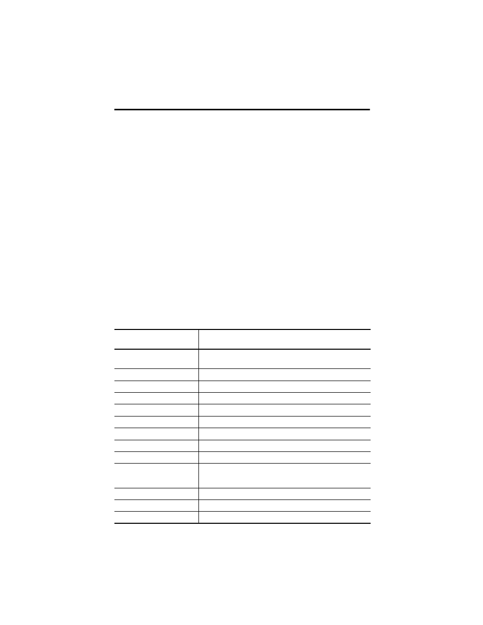
Technical Specifications - Differential Air-pressure Transmitter
Attribute
1414-IPZ10FODAA, 1414-IPZ10FNDAA, 1414-IPD10FNRAA,
1414-CPZ10FODAA, 1414-CPZ10FNDAA, 1414-CPD10PNRAA
Pressure ranges
±0.5 in., ±1 in., ±2 in., 0…1 in., 0…2 in., 0…4 in. wc
±1.5 in., ±3 in., ±6 in., 0…3 in., 0…6 in., 0…12 in. wc
Calibration accuracy
± 1% F.S.O.
Measurement type
Differential (two port)
Response time
1 mS maximum
Stability
< ± 1% F.S.O. per year
Thermal effects
< ± 3% over compensated range
Compensated range
10…50 °C (50…122 °F)
Over pressure
20 psi or 2 x range (whichever is greater)
Operating conditions
0…60 °C (32…140 °F), 10…90% RH non-condensing
Media compatibility
Limited only to those that will not attack polyetherimide, silicon,
fluorosilicone, silicone, EPDM, and neoprene seals. Typically dry air or
inert gas but liquid is allowed.
Power supply (at transmitter)
12…28V AC, 15…35V DC (non-isolated half-wave rectified)
Supply current
< 4 mA
Input voltage effect
Negligible over specified operating range