Rockwell Automation 1494V-DS30_DS60_DS100_DS200 Disconnect Switch (30/60A - Series A) (100/200A -Series B or C) User Manual
Page 7
1004063
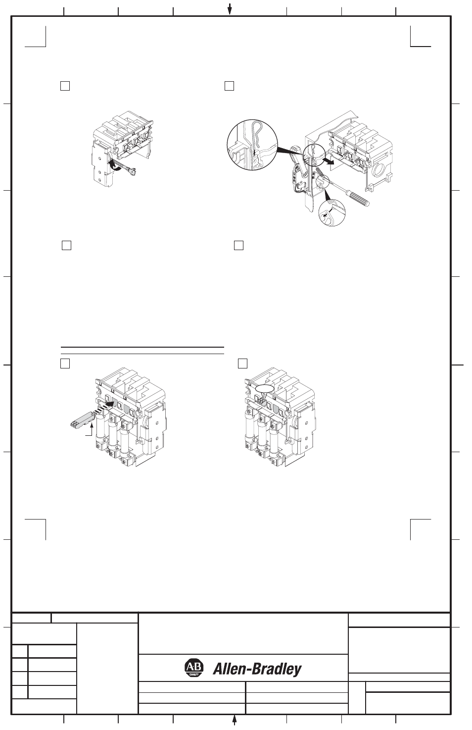
Align
Arrows
Auxiliary Contact Installation
Click
DISCONNECT SWITCH AND ACCESSORY
INSTALLATION INSTRUCTION SHEET
1
42052-064
OF
N/A
N/A
N/A
REVISION
AUTHORIZATION
DR.
CHKD.
APPD.
DATE
DATE
DATE
E - DOC
LOCATION: MILWAUKEE, WISCONSIN U.S.A.
B-vertical.ai
DWG.
SIZE
SHEET
B
1
2
3
4
5
6
7
8
A
B
C
D
E
F
G
H
REFERENCE
DIMENSIONS APPLY BEFORE
SURFACE TREATMENT
(DIMENSIONS IN INCHES)
TOLERANCES UNLESS
OTHERWISE SPECIFIED
.XX:
.XXX:
ANGLES:
42052
THIS DRAWING IS THE PROPERTY OF
ROCKWELL INTERNATIONAL CORPORATION
OR ITS SUBSIDIARIES AND MAY NOT BE COPIED,
USED OR DISCLOSED FOR ANY PURPOSE
EXCEPT AS AUTHORIZED IN WRITING BY
ROCKWELL INTERNATIONAL CORPORATION
---------------
---------------
---------------
---------------
---------------
---------------
7
9
6
Left Hand Operation
7
1
2
Place the disconnect handle in the "ON" position. Insert the
ears of rod into the primary link of the handle and install the
hitch pin as shown below.
Install connecting rod in mechanism and thread in
clockwise (9) full turns.
(7)
Connecting Rod Adjustment Procedure
8
9
"ON" Position
a) Move disconnect handle to the "ON" position.
b) If switch does not fully close, return handle to "OFF"
position.
c) Remove hitch pin and disengage the connectiong rod
from the primary link.
d) Turn connecting rod counter-clockwise (1) full turn.
e) Re-engage connecting rod in primary link of handle,
insert hitch pin and re-test
f) Repeat 4a - 4e as necessary.
"OFF" Position
g) Move disconnect handle to the "OFF" position.
h) If switch does not fully open, return handle to "ON" position.
j) Remove hitch pin and disengage the connectiong rod from the
primary link.
k) Turn connecting rod clockwise (1) full turn.
l) Re-engage connecting rod in primary link of handle, insert
hitch pin and re-test
m) Repeat 5g - 5l as necessary.
Important: Before installing auxiliary contact, disconnect switch must be in "Off" position.