Rockwell Automation 1397 Blower Motor Starter Inst. User Manual
Page 4
1397 Blower Motor Starter
4
1397-5.20 April, 1998
3
REMOVE
Man|Aut
16
A
18
13
15
6
4
2
R
R
0
95
96
97
98
T1
T2
T3
5
-
13
2
-2
T1
3
-4
T2
4
-6
T3
5
-
14
REPLACE WITH
LITTLEFUSE, TYPE CCMR, 600V 2.5A
13FU
14FU
15FU
2
-1
L1
3
-3
L2
4
-5
L3
283
282
4FU 5FU 6FU 7FU 8FU
183
182
181
P8
1
2
2
L2 L3
L1
TORQUE
14-10GA 35 LB.-IN.
0 GA 48 LB.-IN.
SPEC
GND
!
DANGER
RISK OF ELECTRICAL SHOCK. DISCONNECT INPUT
POWER BEFORE SERVICING EQUIPMENT.
P/N 33145
Man|Aut
16
A
18
13
15
6
4
2
R
R
0
95
96
97
98
T1
T2
T3
5
-
13
2
-2
T1
3
-4
T2
4
-6
T3
5
-
14
REPLACE WITH
LITTLEFUSE, TYPE CCMR, 600V 2.5A
13FU
14FU
15FU
2
-1
L1
3
-3
L2
4
-5
L3
DANGER
CIRCUIT BREAKER DOES NOT DISCONNECT INCOMING A0
LINE POWER IT ONLY PROVIDES DC FAULT PROTECTION.
LE DISCONECTEUR NE COUPTE PAS L'AUTOMENTATION DU SPOTEUR IL NES
SERT QUE A ASSURER UNE PROTECTION CONTRE LES DESFAULTS DC.
810903-2424
283
282
4FU 5FU 6FU 7FU 8FU
183
182
181
RISK OF SHOCK
REPLACE AFTER
SERVICING
DANGER
!
❐
1
Disconnect t wires 181, 182
&
183 from the back of the Blower Motor Starter fuse
block and discard them.
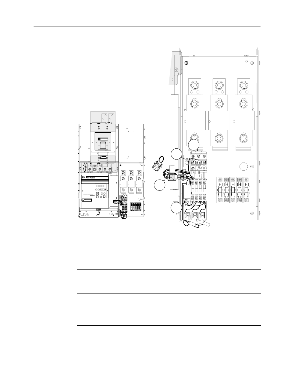
100-150HP/230V and
200-300HP/460V Drive Installation
❐
2
Remove and lock-out all incoming power to the drive. Loosen the (2) phillips head
screws on the molded fuse block and slide the kit’s keyed mounting slots over the
screws. Torque to 6.22 N-m (55 lb-in.).
❐
3
Locate jumper connector assembly P8. Remove the jumper plug and connect
jumper assembly P8 to the Blower Motor Starter’s matching connector.