4a 4b, Man|aut 16, T1 3 – Rockwell Automation 1397 Blower Motor Starter Inst. User Manual
Page 3: T2 4, T3 5, L1 3, L2 4
1397 Blower Motor Starter
3
1397-5.20 April, 1998
3
REMOVE
GRD
A1
45
P4
P4
P4
S4
S4
S4
181
182
183
Man|Aut
16
A
18
13
15
6
4
2
R
R
0
95
96
97
98
T1
T2
T3
5
-
13
2
-2
T1
3
-4
T2
4
-6
T3
5
-
14
REPLACE WITH
LITTLEFUSE, TYPE CCMR, 600V 2.5A
13FU
14FU
15FU
2
-1
L1
3
-3
L2
4
-5
L3
L1
L2
L3
GRD
A1
45
181
182
183
Man|Aut
16
A
18
13
15
6
4
2
R
R
0
95
96
97
98
T1
T2
T3
5
-
13
2
-2
T1
3
-4
T2
4
-6
T3
5
-
14
REPLACE WITH
LITTLEFUSE, TYPE CCMR, 600V 2.5A
13FU
14FU
15FU
2
-1
L1
3
-3
L2
4
-5
L3
L1
L2
L3
P8
181/L1
182/L2
183/L3
2
2
1
4a
4a
4b
4b
5
❒
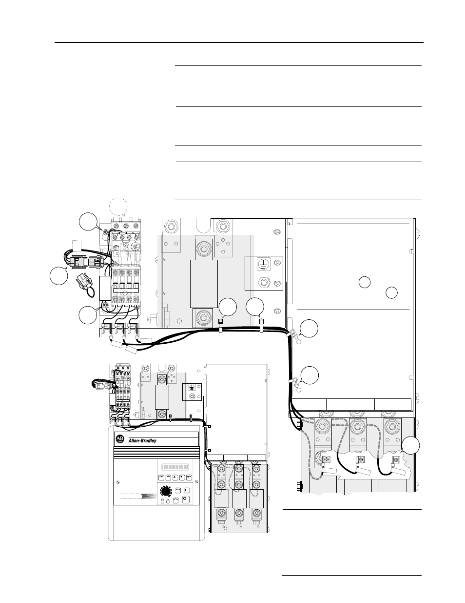
4
Connect and route the
leads of the long
3-conductor wire harness
from the bottom of the
Blower Motor Starter using
the wire ties
and harness anchors
included with the kit.
4a
4b
❐
1
Disconnect t wires 181, 182
&
183 from the back of the Blower Motor
Starter fuse block and discard them.
40-75HP/230V and
75-150HP/460V
Drive Installation
❐
2
Remove and lock-out all incoming power to the drive. Loosen the (2)
phillips head screws on the molded fuse block and slide the kit’s
keyed mounting slots over the screws. Torque to 6.22 N-m (55 lb-in.).
❐
3
Locate jumper connector assembly P8. Remove the jumper plug and
connect jumper assembly P8 to the Blower Motor Starter’s matching
connector.
❐
5
Continue routing the wire harness
under the drive’s line fuse panel and
connect the leads to the spade
connectors on the underside of the
top end of the line fuse connectors
as shown.