Installation requirements, Continued), I/o expansion card connector j1 – Rockwell Automation 1397-L11 I/O Expansion Card User Manual
Page 5: Pulse encoder interface card, Pan head screw pan head screw, I/o expansion card
1397 – 5.19 August, 2000
1397 I/O Expansion Card
5
Installation
Requirements
(continued)
J17
38
38
39
39
40
40
41
41
42
42
43
43
44
44
50
50
51
51
52
52
53
53
54
ANALOG
OUTPUT 1
J14
M
A
V
54
55
55
56
56
57
57
58
58
59
59
60
60
61
61
62
62
63
63
64
64
65
65
66
66
67
67
68
68
69
69
68
68
69
69
IOUT
SOURCE
INT EXT
J15
J11
J12
4-20
PARK
VOLTS
V
M
A
(ANALOG INPUT 1)
10-50
J5
J6
J7
J8
J9
J10
J2
J1
I/O Expansion Card
Pan
Head
Screw
Pan
Head
Screw
I/O
Expansion
Card
Connector J1
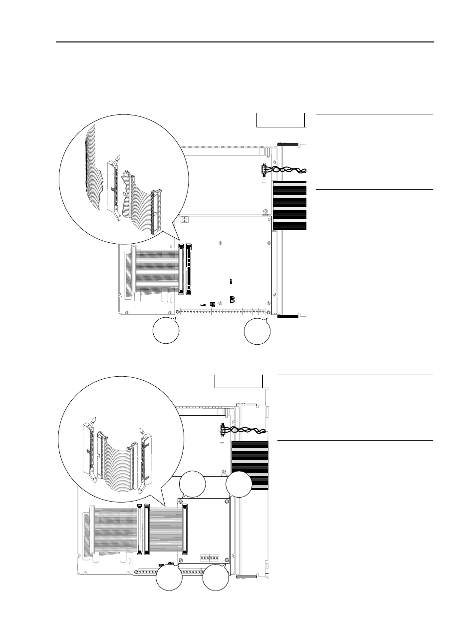
❏ 4 Install the I/O Expansion
Board in the drive carrier
using the (2) pan head
screws provided, then plug
the middle ribbon cable
connector into J1.
J17
38
38
39
39
40
40
41
41
42
42
43
43
44
44
50
50
51
51
52
52
53
53
54
ANALOG
OUTPUT 1
J14
M
A
V
54
55
55
56
56
57
57
58
58
59
59
60
60
61
61
62
62
63
63
64
64
65
65
66
66
67
67
68
68
69
69
68
68
69
69
IOUT
SOURCE
INT EXT
J15
J11
J12
14-20
PARK
VOLTS
V
M
A
(ANALOG INPUT)
J5
J6
J7
J8
J9
J10
J1
74
74
75
75
76
76
71
71
72
72
73
73
J6
J5
+15V
A
COM
ANOT B BNOT
+15V
A
COM
ANOT B BNOT
J2
J1
Pulse
Encoder
Interface
Card
Pan
Head
Screw
Pan
Head
Screw
Pan
Head
Screw
Pan
Head
Screw
Pulse
Encoder
Interface
Card
Connector J1
I/O
Expansion
Card
Connector J2
PULSE ENCODER RIBBON CABLE
❏ 5 If a Pulse Encoder Interface Board is
used, it is mounted piggy-back on the
I/O Expansion Board and connected
using hardware included with the Pulse
Encoder Interface kit.
If a Pulse Encoder Interface Option is also required, complete both
steps 4 and 5.