Rockwell Automation 1485 DeviceBox Tap User Manual
Page 4
4
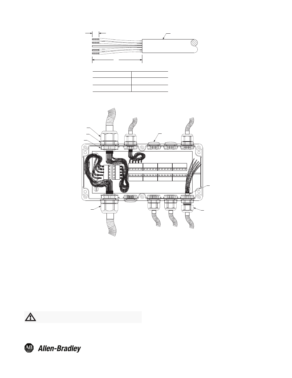
Figure 7: Recommended Cable Stripping for Installation into DeviceBox Tap
A
Cable Jacket
7.9mm (5/16in)
Dimension A"
Trunk Cable
102mm (4in)
Trunk Cable
102mm (4in)
Drop Cable
51mm (2in)
Figure 8: Wiring 8-Port DeviceBox Tap
Plug and Nut
End of Cable Jacket Should
Protrude Approx. 1/8in
Loosened
Gland Nut
Tightened
Gland Nut
Gland Nut
Flange Hex
Locking Nut
1. To install trunk cable into DeviceBox tap cut and strip gray
PVC cable back approximately 4 inches (see Figure 7)
and insert through large cable gland.
2. Loosen gland nut and insert cable until approximately 1/8
inch of cable jacket protrudes.
3. Then firmly tighten gland nut to provide strain relief and
sealing. Caution: The flange hex must be held with the
cable gland wrench during tightening.
4. The bare wire ends should be firmly twisted to eliminate
loose strands and each lead looped approximately as
shown, to allow insertion into the clamping cavity of the
terminal block. (See Figure 2 for color codes.)
. .
5. To attach cable to terminal strips, press down on cage
clamp, insert wire and release cage clamp. Repeat
process for remaining four wires.
6. To install drop cable into DeviceBox tap, cut and strip drop
cable back approximately 2 inches (see Figure 7). Note:
Repeat previous trunk cable instructions.
7. After all cables are terminated, the cover should be
installed and securely tightened to ensure washdown
rating. Seal unused drop positions with nylon plugs, o-ring
seals, and nuts (included in accessory kit).
Follow same installation instructions for 2- and 4-port
DeviceBox taps.
All external wiring should conform to the national electric code
and applicable local codes.
ATTENTION: Be certain to use insulating tubing
(included in accessory kit) on bare drain wire.
Publication 75006-279-01(C)
December 2004
Printed in USA