Installation – Rockwell Automation 1397 400-600HP AC Line Disconnect Inst. User Manual
Page 5
1397 600HP AC Line Disconnect
5
1397-5.30 July, 1998
BLOWER MOTOR
STARTER KITS
283
5FU
4FU
282
281
288
289
ON
Plastic
AC Line
Input
Cover
OFF
Cover
Screw
Cover
Screw
81
82
83
181
182
183
AC Line
Terminal
7/16" Flat Washer
7/16" Split Lockwasher
7/16" x 1" Bolt
— (6) Places —
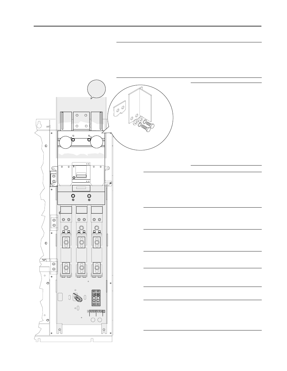
Installation
❐
15
Remove the disconnect’s top lug cover by loosening the (2)
captive cover screws. Install the AC line terminals removed in
Step 3
onto the disconnect’s line connections. Use (2) 7/16" flat
washers, (2) split lockwashers
&
(2) 1" bolts for each AC line
terminal. Tighten all bolts to 34Nm (300lb.-in.).
❐
17
If you are using the AC line compression terminals,
connect the incoming power cables. Use a 1/4 inch
Allen wrench to tighten the screws on the
compression terminals to 33.9 Nm (300 in-lb).
❐
19
If the disconnect is the main disconnect, attach a
label reading MAIN.
❐
20
Install the plastic AC line input cover by inserting
its feet into the slots on the mounting panel. Squeeze
the cover slightly to seat the upper feet, then pull
down to secure cover in place.
❐
16
If you are using AC line
compression terminals,
proceed to step 17.
If you
are using the AC line bus bar
terminals (removed in step
3) connect them to the
disconnect switch line
connections using a 7/16 x
1" bolt, 7/16" split washer
and 7/16" flat washer.
Tighten to 39 Nm (346
in-lb).
❐
18
Replace the disconnect’s top lug cover and tighten
the (2) captive screws to secure it in place.