Rockwell Automation 875 Capacitive Proximity Sensor User Manual
Page 3
Target Considerations
Standard Target
The standard target is a grounded, 1mm-thick square of mild
steel. The side lengths of a standard target are equal to either
the diameter/width of the sensor face or three times the
nominal sensing distance, whichever is greater.
Shielded vs. Unshielded
Shielded capacitive sensors can be used to sense either
conductive (metal, water) or nonconductive (wood, paper,
glass, plastic) materials. Their internal ground allows them to
detect grounded or ungrounded targets. It also makes them
more susceptible to dust and moisture in the environment than
unshielded sensors.
Unshielded capacitive sensors are used primarily to sense
grounded, conductive materials at maximum sensing
distances. They are less sensitive to nonconductive materials
than shielded sensors. This makes them able to detect
conductive materials through a nonconductive material, such
as water inside a plastic tank. In this case, the nonconductive
material can be no thicker than the sensor’s sensing distance.
(Note: capacitive sensors cannot sense through metals.) Dust
and moisture in the atmosphere have less effect on
unshielded sensors than on shielded models.
Grounding
Targets should be grounded for most reliable sensing. If a
ground path to the target is not available, shielded sensors are
recommended. When attempting to detect nonconductive
materials with an unshielded sensor, a path to ground is
required.
Dielectric Constants
The dielectric constant is one of the material properties of a
target. Materials with higher dielectric constants are more
easily detected by capacitive sensors and are therefore
detected at greater sensing distances than those with low
constants. See page 4 for a list of common industrial materials
and their dielectric constants.
Correction Factors
Correction factors are multipliers which are determined by a
target’s mass, material, and grounding state. To calculate an
approximate sensing distance for an application, multiply the
nominal sensing distance S
n
by the correction factor for that
application’s target. The table below shows some typical
correction factors.
Correction Factors for Common Materials
Grounded metals
1.0
Ungrounded metals
0.85
Water
1.0
Glass
0.55
Paper (1 ream, 500 sheets)
0.55
Wood
0.45
Stone
0.65
Ceramic tile
0.25
PVC
0.15
Environmental Factors
Capacitive sensors can be compromised by humidity as well
as moisture on the sensor’s face. Oil or water droplets on the
sensor face can cause the unit to become unstable. Dust and
moisture in the atmosphere have less of an effect on
unshielded sensors than on shielded models.
Mounting Considerations
The control must be securely mounted on a firm, stable
surface or support. A mounting configuration which is unstable
or subject to excessive vibration may cause intermittent
operation.
Shielded vs. Unshielded
Shielded sensors can be mounted flush with surrounding
materials. Unshielded sensors must be mounted such that the
area around the sensing face is free of any material which
could trigger the sensor. Minimum clearance in all directions
should be equal to the diameter or width of the sensor.
Spacing Between Devices
When two shielded or unshielded sensors are facing each
other, they must be mounted far apart to avoid interference.
Minimum spacing should be eight times the housing diameter
or width. When two shielded sensors are mounted side by
side, the minimum distance between them must be greater
than one diameter or width. When two unshielded sensors are
mounted side by side, the distance between them should be
at least four times their diameter or width. See Dimensions
section for housing sizes.
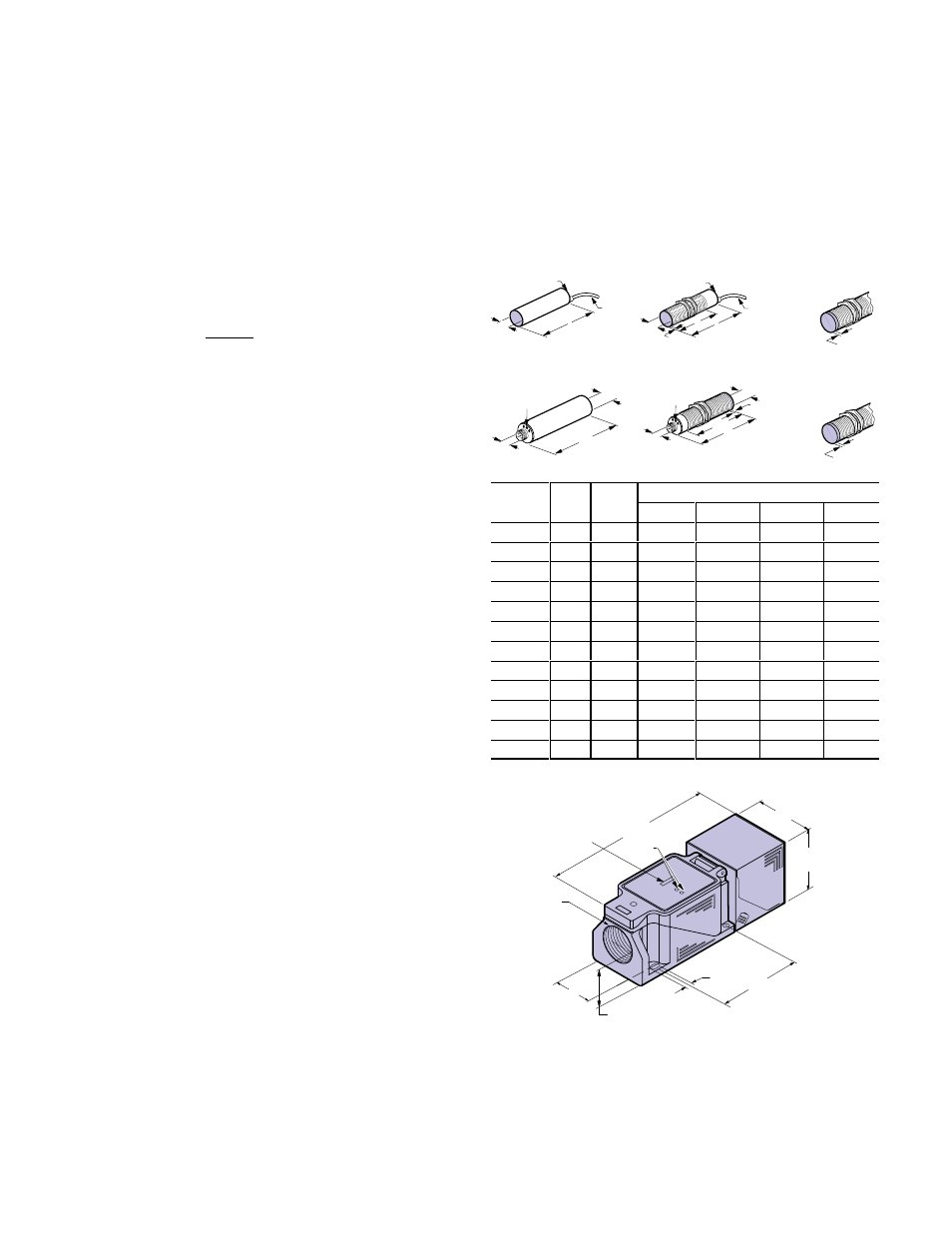
Dimensions
Cylindrical Style
Potentiometer
and LEDs
B
A
2m
(6.5ft)
Potentiometer
and LEDs
C B
D
A
2m
(6.5ft)
D
Unshielded
Threaded
Version
M12 x 1
M8 x 1 (pico)
M12 x 1 (micro)
C
B
A
Potentiometer
and LEDs
D
A
B
Potentiometer
and LEDs
Unshielded
Threaded
Version
D
mm(inches)
Thread
Shld
Conn.
A
B
C
D
M12x1
Y
cable
12(0.47)
61.5(2.42)
40.5(1.59)
N/A
M12x1
Y
pico
12(0.47)
63.5(2.50)
40.5(1.59)
N/A
M18x1
Y
cable
18(0.71)
81.7(3.22)
60.7(2.39)
N/A
M18x1
Y
pico
18(0.71)
81.7(3.22)
60.7(2.39)
N/A
M18x1
N
cable
18(0.71)
81(3.19)
60(2.36)
20(0.79)
M18x1
N
pico
18(0.71)
81(3.19)
60(2.36)
20(0.79)
M30x1.5
Y
cable
30(1.18)
82(3.23)
61(2.40)
N/A
M30x1.5
Y
micro
30(1.18)
82(3.23)
61(2.40)
N/A
M30x1.5
N
cable
30(1.18)
80.5(3.17)
59(2.32)
20(0.79)
M30x1.5
N
micro
30(1.18)
80.5(3.17)
59(2.32)
20(0.79)
N/A
N
cable
34(1.34)
85(3.35)
N/A
N/A
N/A
N
micro
34(1.34)
82(3.23)
N/A
N/A
Limit Switch Style
120.0
(4.72)
LEDs
41.5
(1.63)
41.5
(1.63)
Conduit Entrance
1/2-14 NPT
15.9
(0.63)
30.0
(1.18)
60.0
(2.36)
7.3
(0.29)
Note:Head can be rotated in 15
°
increments to provide 24 sideĆ
sensing positions or rotated for top sensing.
NO/NC and PNP/NPN
Selector Switches