Rockwell Automation 875 Capacitive Proximity Sensor User Manual
Rockwell Automation Equipment
INSTALLATION INSTRUCTIONS
BULLETIN 875C, 875CP, 875L CAPACITIVE PROXIMITY SENSOR
IMPORTANT: SAVE THESE INSTRUCTIONS FOR FUTURE USE.
!
ATTENTION: Solid-state devices can be susceptible to radio frequency (RF) interference depending on the power
and the frequency of the transmitting source. If RF transmitting equipment is to be used in the vicinity
of the solid state devices, thorough testing should be performed to assure that transmitter operation is
restricted to a safe operating distance from the control equipment and its wiring.
!
ATTENTION: If a hazardous condition can result from unintended operation of this device, access to the sensing
area should be guarded.
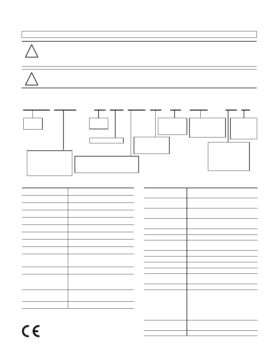
Part Number Configuration
875 CP – D M 30 N P 34 – A 2
Capacitive
Proximity
Sensor
A = AC
D = DC
M = Smooth barrel
P = PNP
N = NPN
E = Selectable
Housing diameter (mm)
(cylindrical types)
Head width (mm) (limit
switch style types)
Cable length (m)
Number of pins
Number of
terminals
N = Normally open
C = Normally closed
E = Selectable
C = Cylindrical metal body
(shielded)
CP = Cylindrical plastic body
(unshielded)
L = Limit switch style
Nominal sensing distance (in mm)
2, 5, or 10mm = shielded construction
4, 8, 20, or 30mm = unshielded construction
A = PVC cable
D = DC micro connector
P = Pico connector
R = AC micro connector
T = Terminal chamber
Specifications—AC Models
Max. Load Current 300mA
Inrush Current 2A
Leakage Current 3.5mA
Operating Voltage 20-250V
Voltage Drop <10V
Repeatability
≤
10%
Hysteresis
≤
20%
Max. Switching Frequency 15Hz
Transient Noise Protection Incorporated
Enclosure NEMA 12, IP65 (IEC 529)
Plastic or nickel-plated brass
Approval CE marked
Connections Cable
2Ćmeter length
2Ćconductor PVC
QuickĆDisconnect
3Ćpin micro
LEDs Green: Power
Yellow: Output
Operating Temperature -25
°
C to +70
°
C (-13
°
F to +158
°
F)
Allen-Bradley capacitive sensors are manufactured and tested
to the international standard IEC 947–5–2.
Specifications—DC Models
Max. Load Current 12, 18mm
30, 34mm, limit switch style
200mA
400mA
Leakage Current 12mm
18, 30, 34mm, limit switch style
0.3mA
0.1mA
Operating Voltage 12mm
18, 30, 34mm, limit switch style
10-36V
10-60V
Voltage Drop 12, 18mm
30, 34mm, limit switch style
<2V
<3V
Repeatability
≤
10%
Hysteresis
≤
20%
Max. Switching Frequency 12, 18, 30, 34mm
limit switch style
25Hz
40Hz
Transient Noise Protection Incorporated
Reverse Polarity Protection Incorporated
Short Circuit Protection Incorporated
Overload Protection Incorporated
Enclosure NEMA 12, IP65 (IEC 529)
Plastic or nickelĆplated brass
Approval CE marked
Connections Cable
2Ćmeter length
3Ćconductor PVC
Quick-Disconnect
4Ćpin micro
3Ćpin pico
Conduit Opening
1/2Ć14 NPT internal
thread with screw
terminals
LEDs Green: Power
Yellow: Output
Operating Temperature -25
°
C to +70
°
C (-13
°
F to +158
°
F)