Wiring, Wiring diagrams for ac switches, Wiring diagrams for dc switches – Rockwell Automation 875 Capacitive Proximity Sensor User Manual
Page 2: Wiring switches in series, Wiring switches in parallel, Sensing distance adjustment
Wiring
All external wiring should conform to the National Electric
Code and applicable local codes. Connect the proximity
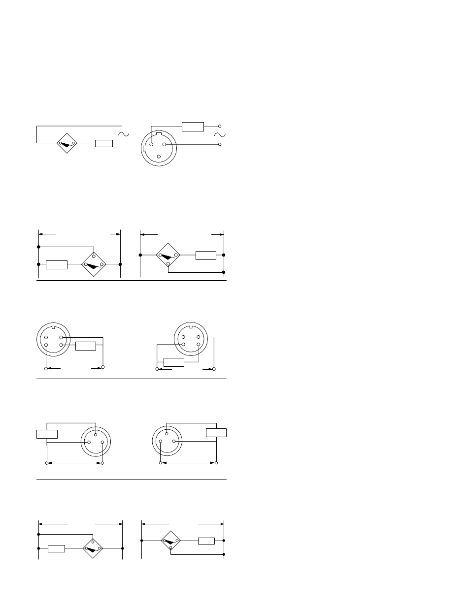
switch to the power supply and load as shown in the wiring
diagrams below. If the positive (+) and negative (–) wires are
reversed, the switch will not operate properly. The sensor will
not be damaged because it is equipped with reverse polarity
protection.
Wiring Diagrams for AC Switches
Cable
Micro-Connector
Normally Open or Normally Closed
Note: Load can be switched to pin 2.
Note: Load can be switched to black wire.
Load
Black
Blue
Load
1
2
3
Wiring Diagrams for DC Switches
Cable
+
10-36V DC (12mm)
10-60V DC (18-34mm)
-
Load
Blue
+
-
Black
+
-
Load
Brown
-
+
Black
Blue
Brown
NPN (Sinking)
PNP (Sourcing)
Normally Open or Normally Closed
10-36V DC (12mm)
10-60V DC (18-34mm)
Micro-Connector
Normally Open or Normally Closed
-
+
Load
2 1
3 4
PNP (Sourcing)
-
+
-
+
Load
2 1
3 4
NPN (Sinking)
-
+
10-60V DC
10-60V DC
Pico-Connector
Normally Open or Normally Closed
10-36V DC (12mm)
10-60V DC (18mm)
10-36V DC (12mm)
10-60V DC (18mm)
PNP (Sourcing)
4
3
1
+
Load
-
-
+
NPN (Sinking)
4
3
1
-
Load
+
+
-
Terminal Chamber
Normally Open or Normally Closed
NPN (Sinking)
PNP (Sourcing)
+
10-60V DC
-
Load
T3
+
-
T2
+
-
Load
T1
-
+
T2
T3
10-60V DC
T1
Wiring Switches in Series
Switches can be connected in series with a load. For proper
operation, the voltage across the energized load must be less
than or equal to the minimum supply voltage minus the
voltage drops across all sensors. The load will be energized
only when all switches are closed.
Wiring Switches in Parallel
Switches can be connected in parallel to energize a load. The
sum of the maximum leakage currents for the switches must
be less than the maximum off-state current of the load device.
The load will be energized when one or more of the switches
are closed.
Sensing Distance Adjustment
The sensing distance of an Allen-Bradley capacitive proximity
sensor can be adjusted via a twenty-turn potentiometer at the
rear of the sensor housing. Although this is a clutched
potentiometer, it does not emit an audible “click” when turned
beyond its range.
The maximum sensing distance for each sensor can be
determined using the part number configurator on page one. If
the sensing distance is set higher than the maximum, the unit
may lock in the triggered state. The minimum distance to
which each sensor can be adjusted is listed in the table below.
Nominal sensing distances are measured using a standard
target (see Target Considerations).
Minimum Adjusted Sensing Distances
12mm metal housing:
0.4mm
18mm metal housing:
1.0mm
18mm plastic housing:
2.0mm
30mm metal housing:
2.0mm
30mm plastic housing:
5.0mm
34mm plastic housing:
7.0mm
limit switch style housing:
10.0mm
This unit is not designed for reliable operation when adjusted
to distances shorter than those stated above.
Adjustment Procedure:
1. Mount the sensor on a stable surface or support (see
Mounting Considerations).
2. Apply power to the sensor per wiring diagrams (see
Wiring). Check that the green “power” LED turns on.
3. Determine a desired sensor-to-target distance which is
between the unit’s rated minimum and maximum sensing
distances (see Target Considerations and Dielectric
Constants).
4. Multiply this desired sensing distance by 1.2 and place the
target at the resulting new distance from the sensor.
Check the yellow “output” LED status.
5A. (Normally Open Models Only) If the yellow LED is off, turn
the potentiometer slowly clockwise until the LED turns on.
If the yellow LED is already on, turn the potentiometer
counterclockwise until the LED turns off, then slowly
clockwise until the LED turns on again.
5B. (Normally Closed Models Only) If the yellow LED is on,
turn the potentiometer slowly clockwise until the LED turns
off. If the yellow LED is already off, turn the potentiometer
counterclockwise until the LED turns on, then slowly
clockwise until the LED turns off again.
6. Remove the target and check that the yellow LED turns off
for normally open models and on for normally closed
models.
7. Place the target at the original desired sensor-to-target
distance determined in step 3. If the yellow LED turns on
for normally open models and off for normally closed
models, the sensor is correctly adjusted.