V. wiring diagrams (continued) – Rockwell Automation 1492- 1771-N Series I/O to 1756 ControlLogix I/O User Manual
Page 13
V. Wiring Diagrams (Continued)
There are several key application considerations and system specifications (bottom of drawing) when
using these components (conversion module, cable and input module). Read and understand these
considerations before installation.
WARNING
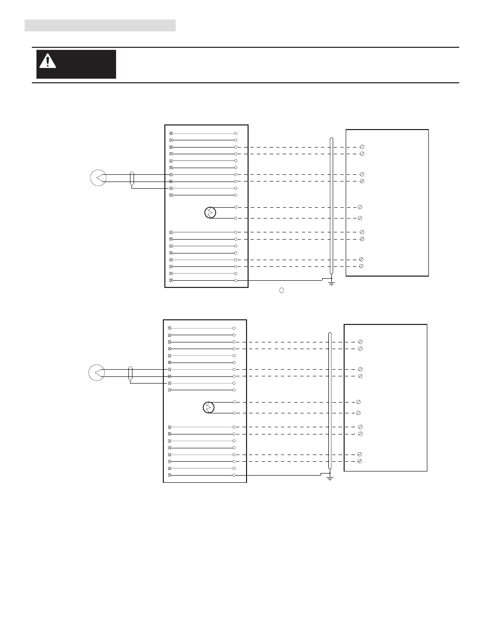
Conversion: 1771-NT1 (1) To 1756-IT6I (2) (Thermocouple)
Using Existing 1771-RT41 Interface Module
(13)
B1
A1
B2
B3
A2
A3
B4
B5
A4
A5
B6
B7
A6
A7
B8
B9
A9
A8
3
W1
SH
I4
I3
I2
I1
R4
R3
R2
R1
O4
O3
O2
O1
S4
S3
S2
S1
15
16
19
18
25
24
21
22
+
-
Black
Red
Green
Brown
White/Black
White/Red
Yellow
Violet
THERMOCOUPLE
5
6
8
7
9
10
11
12
RTN-0
RTN-1
RTN-2
RTN-3
IN-0
IN-2
IN-3
IN-1
CJC+
CJC-
Thermocouple
10
14
B1
A1
B2
B3
A2
A3
B4
B5
A4
A5
B6
B7
A6
A7
B8
B9
A9
A8
W1
SH
I4
I3
I2
I1
R4
R3
R2
R1
O4
O3
O2
O1
S4
S3
S2
S1
15
16
19
18
25
24
21
22
+
-
Black
Red
Green
Brown
White/Black
White/Red
Yellow
Violet
THERMOCOUPLE
1
5
6
2
7
11
8
12
RTN-0
RTN-1
RTN-2
RTN-3
IN-0
IN-2
IN-3
IN-1
CJC+
CJC-
Thermocouple
10
14
14
1
14
1
Cable “B”
1492-CONACAB020N5
Cable “A”
1492-CONACAB020N5
Interface Module
1771-RT41
Interface Module
1771-RT41
1756-IT6I
1756-IT6I
PN-107134
DIR 10000165561 (Version 01)
Publication 1492-IN104B-EN-E
Conversion Module Installation and Application Considerations
Cables are available in 2.0m, or 5.0m
Terminals starting with A are the lower row of terminals, B terminals are the upper row.
Follow your PLC Analog User Manual for proper shield grounding instructions.
RTN terminals are internally connected on the 1756-IT6I.
Terminals w1, w2, w3, are spares used for field wire convenience. NOTE: This is only true for module RTP4. The Bul.
1492 cable does not connect to these terminals.
This conversion solution requires replacement of the exisiting (1) 1771-RTP1 interface module with (2) 1771-RT41
interface modules. Each 1771-RTP1 and RT41 module has there own cold junction compensation thermocouple attached to
the interface module.
[Reference Doc: 41171-076 (Version 00)]