Adding or changing contact cartridges (continued), Operation – Rockwell Automation 700-RTC Type RTC Fixed Time Solid-State Timing Relays User Manual
Page 3
Publication 700-IN004C-EN-P - October 2009
Bulletin 700 Type RTC Fixed Time Solid-State Timing Relays 3
Adding or Changing
Contact Cartridges
(continued)
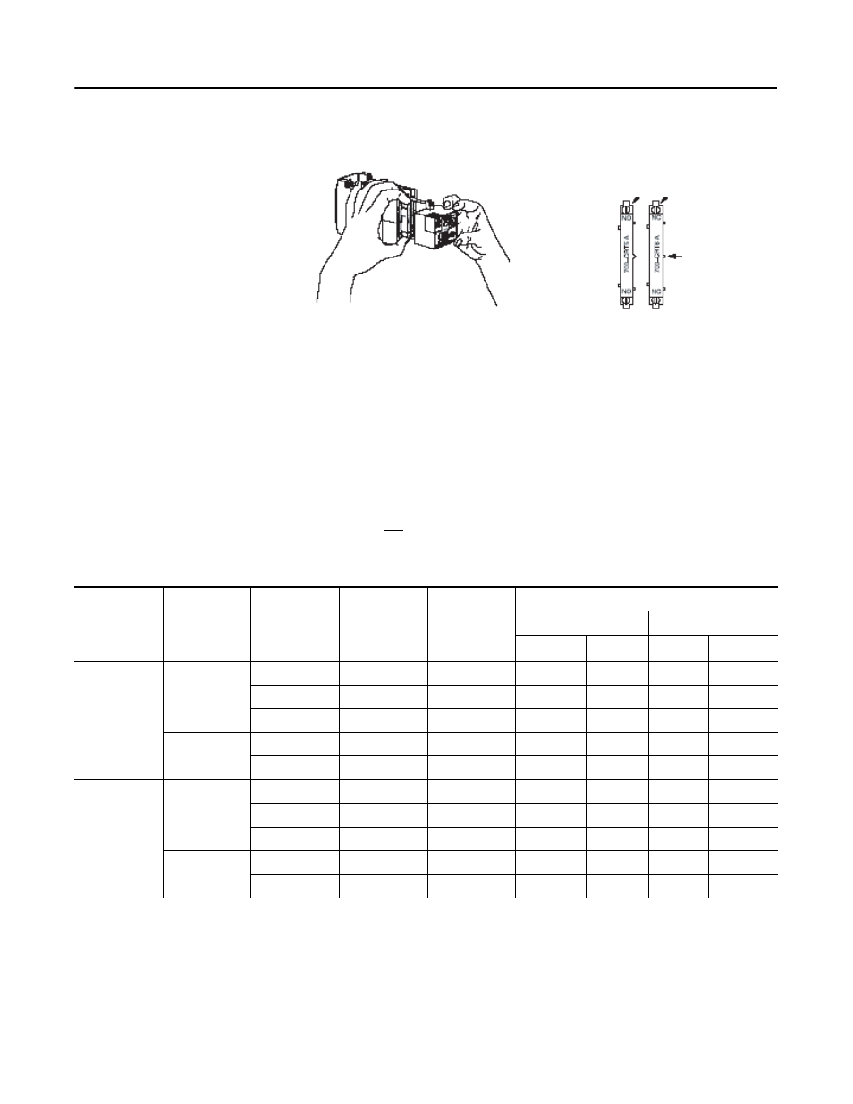
Figure 1. Removing and Orientation of Cartridges
Operation
Table 1 outlines timer operation in both the on-delay and off-delay modes.
The red LED indicator on the front housing of the timer gives visual
indication of timing, timed out, and reset or stable timer conditions. At certain
settings, there may be a slight delay in the LED operation. The timing
sequence is not affected by this delay.
Table 1 Timer Operation
Note:
When the timer is energized or times out in the on-delay mode, an
N.O. contact may close before an N.C. contact opens; this can occur because
of inherent operating characteristics. Similarly, when the timer is de-energized
or times out in the off-delay mode, an N.C. contact may close before an N.O.
opens. Assured contact overlap or non-overlap cannot be provided in the same
device.
Orientation of cartridges
Method of removing cartridge
Projection for Keying
Insert cartridge with this end at top of timer
Operating
Mode
Power
(Terminals
L1-L2)
Voltage
(Applied to
Initiate
Terminal P)
Timer Status
Red LED
Indicator
Contact Cartridge Statue
Instantaneous
Timed
N.O
N.C
N.O
N.C
On-delay
On
No
Reset
Off
Open
Closed
Open
Closed
Yes
Timing
Flashing
Closed
Open
Open
Closed
Yes
Timed Out
On
Closed
Open
Closed
Open
Off
No
Stable
Off
Open
Closed
Open
Closed
Yes
Stable
Off
Closed
Open
Open
Closed
Off-delay
On
Yes
Reset
On
Closed
Open
Closed
Open
No
Timing
Flashing
Open
Closed
Closed
Open
No
Timed Out
Off
Open
Closed
Open
Closed
Off
No
Stable
Off
Open
Closed
Open
Closed
Yes
Stable
Off
Closed
Open
Open
Closed