Maximum torque specification, Minimum distance between sensors, Misalignment curve – Rockwell Automation 440N SensaGuard Magnetically Coded NonContact Switch (MC2) User Manual
Page 5: Direction of approach, 50mm
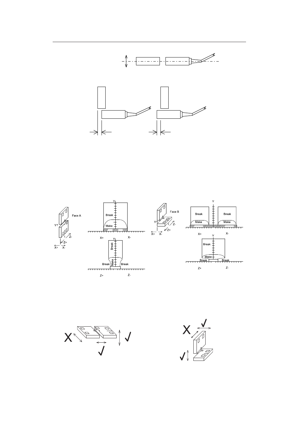
4.2
Maximum Torque Specification
- 1 N
•
M (8.86 in
•
lbs), use non-magnetic fixing hardware.
4.3
Minimum Distance Between Sensors
- 50mm
4.4
Misalignment Curve
4.5.
Direction of Approach
72697 Issue 4 EO: 28485
Magnetically Coded Non Contact Switch Installation Instructions 5
0
0
0
-4
-8
-12
-16
-20
4
8
-24
12
16
20
4
8
12
16
0
-4
-8
-12
-16
-20
4
8
-24
12
16
20
4
8
12
16
20
24
20
24
2mm Gap
2mm Gap
0
0
0
-4
-8
-12
-16
-20
4
8
-24
12
16
20
4
8
12
16
0
-4
-8
-12
-16
-20
4
8
-24
12
16
20
4
8
12
16
20
2mm Gap
2mm Gap
2mm Gap
Note: Refer to Technical Specifications for Certification information and ratings.
Sensor
Sensor
Ac
tu
a
to
r
Ac
tu
a
to
r
Sensor
Actuator
To obtain maximum switching
distance center switches +/- 4mm
To prevent damage it is recommended that a 2mm gap
be maintained between the actuator and sensor
To prevent damage it is recommended
between the actuator and sensor
For more detailed misalignment characteristics refer to the misalignment curves
that a 2mm gap be maintained
distance 8 - 14 mm
To obtain maximum switching
distance 8 - 14 mm
Note: To prevent damage to the MC2 it is recommended to leave a 2mm gap between the Sensor and Actuator.
The maximum switching distance and misalignment tolerance will be obtained when the MC2 is mounted on non-fer-
rous material. Mounting the MC2 on ferrous/magnetic material will reduce the switching distances and tolerance to
misalignment.