Caution – Rockwell Automation 140U Q, M frame CB Electronic RMS Trip Unit installation and operation User Manual
Page 3
Page
3
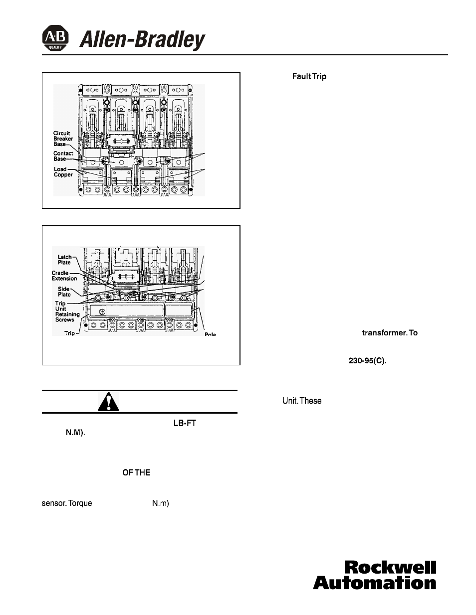
-Contact
Base
-Load
Copper
Fig.
3
Contact Bases and Load Copper
LINE
END
Side
Plate
Trigger
Trip
Unit and
Current
Sensor
Retaining
Screws
Fourth
Unit
LOAD
END
. -.-
Current
Sensor
Fig. 4
Trip Unit Installed in Circuit Breaker
CAUTION
DO NOT EXCEED A TORQUE OF 12
(16.27
EXCESSIVE TORQUING WILL SHEAR
SCREWS.
FAILURE TO APPLY THE REQUIRED TORQUE MAY
LEAD TO EXCESSIVE HEATING AND CAUSE
NUISANCE TRIPPING
CIRCUIT BREAKER.
Screw in and tighten three trip unit retaining screws
(center first) and the screw for the fourth pole current
to 12 Ib-ft (16.27
(see Fig. 4).
Finish installation of the 4-pole Trip Unit by following the
instructions in Section 3.5.
3.3 Ground
Unit Installation
3.3.1 General
Ground fault trip units are supplied from the factory with a
wire harness with pigtail lead connections for a neutral
current sensor (white and grey wires) and a ground fault
alarm relay (yellow and green wires). A neutral current
sensor is provided with each trip unit, and the ground fault
alarm relay is ordered and shipped separately if required.
If the alarm relay is not required, the green and yellow
leads should be cut off before the trip unit is installed in
the breaker.
Electronic RMS Ground Fault Trip Units detect ground
fault currents through Residual Sensing. They are not
designed to use source ground or zero sequence ground
fault sensing methods. If the system neutral is grounded,
but no phase to neutral loads are used, the neutral current
sensor is not necessary. In that case, the white and grey
leads on the trip unit should be cut off before installation.
If the system neutral is grounded and phase to neutral
loads are used, then the neutral current sensor (see Fig. 5)
must be used. It should be connected to the breaker
according to the diagram in Fig. 6. It has the same turns
ratio as the phase current sensors in the trip unit.
Note: The polarity of the sensor connections is
critical. Always observe the polarity markings on the
installation drawings. The polarity markings are
identified as white dots on the
insure
correct ground fault equipment performance, conduct
field tests to comply with National Electric Code
requirements under article
See Section 6.2
for testing instructions.
The optional “Internal Accessories” listed in Section 8.2
are available for installation in a Electronic RMS Ground
Fault Trip
items, if required, must be ordered
separately.
3.3.2 Installation
Plug the wire harness supplied for the neutral current
sensor and ground fault alarm relay (white, grey, yellow
and green wires) into the connector located in the right
pole of the trip unit. With the correct polarity the harness
should snap into place. Do not force the harness into the
connector with the wrong polarity.
Remove trip unit outer pole screws and red plastic
washers from the breaker frame. Discard red plastic
washers (fig. 7). For the M-frame, also remove the load
end trip unit mounting screws from the frame
(fig. 7a).
40752-072(2)
Effective
6/02