Default input and output (i/o) assembly formats – Rockwell Automation 281G ArmorStart Distributed Motor Controller - Getting Started User Manual
Page 11
Publication 280G-QS001A-EN-P - December 2008
11
Using Automap feature with default Input and Output (I/O) assemblies
The Automap feature available in all Rockwell Automation scanners will
automatically map the information as shown below. If manual mapping is
required, the information below can be used to map a device based on the
default configuration.
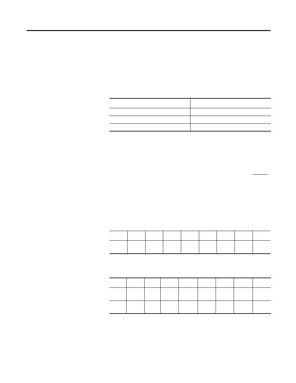
Table 3
Default I/O Messaging Data
Default Input and Output (I/O) Assembly Formats
The I/O assembly formats for the ArmorStart
are identified by the value in
parameter 11 (Consumed IO Assy.) and parameter 12 (Produced IO Assy.).
These values determine the amount and arrangement of the information
communicated to the master scanner. The tables below identify the default
information produced and consumed by DOL (Bulletin 280) and Reversing
(Bulletin 281) devices. For additional formats and advance configurations
please reference the user manual:
Defaults for Standard Distributed Motor Controllers
Table 4
Instance 160 - Default Consumed data for Standard Distributed Motor
Controller Output information arrangement (1 byte)
Table 5
Instance 161 - Default Produced data for Standard Distributed Motor
Controller Input information arrangement (2 bytes)
Default
Message type
Polled
Consumed data size
1 byte (Rx)
Produced data size
2 bytes (Tx)
Byte
Bit 7
Bit 6
Bit 5
Bit 4
Bit 3
Bit 2
Bit 1
Bit 0
0
Not
Used
Not
Used
Not
Used
Not
Used
Not
Used
Fault
Reset
Run Rev
Run Fwd
Byte
Bit 7
Bit 6
Bit 5
Bit 4
Bit 3
Bit 2
Bit 1
Bit 0
0
Not
Used
140M
On
Not
Used
Ready
Running
Rev
Running
Fwd
Warning
Tripped
1
Not
Used
Not
Used
User In 5
User In 4
User In 3
User In 2
User In 1
User In 0