Rockwell Automation 141A Mounting System Temperature Rise Calculation Software Tutorial User Manual
Page 20
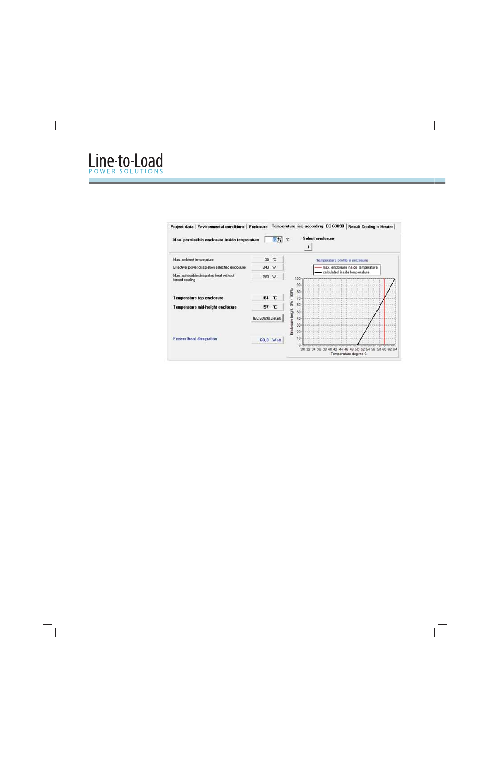
18
In our Example, the calculation shows an excess heat dissipation of 60 W, which would cause a
temperature excess of 4 °C on top of the enclosure.
Let’s try diff erent measures to solve this issue. Make sure you change the settings back to the
original values before trying each solution.
Select a bigger enclosure. If you are not limited by space, this is a very effi
cient method
•
without an infl uence to the ingress protection level of the enclosure type.
–
Go back to the “Enclosure” tab and try it.
For example, an enclosure of
1,000 x 1,600 x 500 solves the issue.
Install air inlet / outlet openings. Air inlet openings of 50 cm
•
2
would solve the issue. It needs
to be more if the effi
ciency is reduced by a fi lter. Th
is measure is not applicable if a high
ingress protection level is required.
Note: Th
e outlet openings need to be at least 1.1 x the cross-section of the inlet openings.
–
Go back to the “Enclosure” tab and try it. Activate the check box “Air inlet opening”
Verify with the customer if the rated ambient temperature must be 35 °C. A reduction to
•
30 °C would solve the issue.
–
Go back to the “Environmental Conditions” tab and try it.
Verify with the customer if the Reduction Factor for the components (or some of them) can be
•
reduced. Experience shows that in many applications the Simultaneity Factor is < 50%.
Note: See User Manual or Help fi le and IEC 60439 / IEC 61439 for more information about
the Reduction Factor
–
Go back to the “Enclosure” tab and select the [ Evaluate ] button. Test how changes in
the Reduction Factor infl uence the power loss.
2.4.1
Measures to Take
in Case of Heat
Dissipation Excess