Rockwell Automation 141A Mounting System Temperature Rise Calculation Software Tutorial User Manual
Page 18
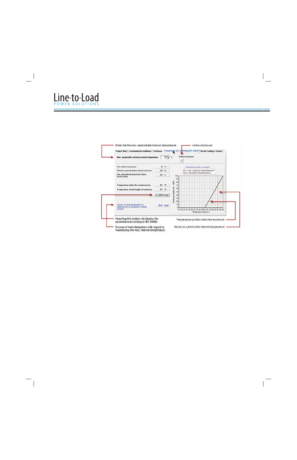
16
Th
is tab shows the result of the temperature rise calculation as a temperature profi le within
the enclosure.
If there are multiple enclosures in a row, there will be a numbered button for each one.
Th
e active enclosure can be selected using the buttons at the top, without having the need to
switch back to the “Enclosure” tab.
IEC 60890 refers to cabinets with natural convection. If devices with integral fans are used, this
assumption no longer applies. Th
e diff erences in temperature within the enclosure are reduced
and the total heat dissipation across the enclosure’s surface is improved.
Th
e maximum permissible internal enclosure temperature is 60 °C by default, but it can be
changed in the upper area of this tab. It is shown as a red limit line in the temperature
profi le diagram.
Th
e maximum ambient temperature is taken from the “Environmental conditions” tab,
the eff ective power loss for the active enclosure from the “Enclosure” tab. Th
e fi eld below that
shows the power loss at which the maximum permissible internal enclosure temperature is
maintained. Th
e diff erence is the excess Watt loss that needs to be dissipated. Th
is is shown on
the bottom left of the window.
Th
e diagram shows the temperature profi le within the enclosure (for enclosures with an eff ective
cooling surface of < 1.25 m
2
, the temperature remains constant in the upper quarter) and
the maximum permissible temperature. To the left of this, the temperature values below the
enclosure’s roof and at mid-height, calculated in accordance with IEC 60890, are displayed.
2.4
“Temperature Rise
According to
IEC 60890” Tab