Connector pins and signal availability, Dimensions [mm (in.) – Rockwell Automation 847H 2.5 in. Diameter Solid Shaft Incremental Encoders User Manual
Page 3
3
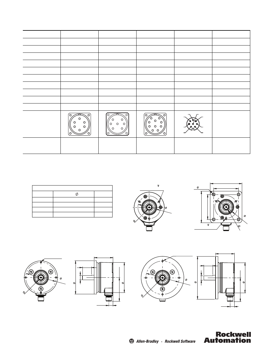
Connector Pins and Signal Availability
Signal Name
MS 6-pin
MS 7-pin
MS 10-pin
M12 8-pin
Cable Wire Colors
V DC
B
D
D
8
Red
Common
A
F
F
7
Black with red band
A output
E
A
A
2
White
AN output
-
-
H
1
Black with white band
B output
D
B
B
4
Blue
BN output
-
-
I
3
Black with blue band
Z
output
C
C
C
6
Green
ZN output
-
-
J
5
Black with green band
Zero set input
-
E
E
-
Yellow
Case
F
G
G
-
Black
Encoder
connectors/
cable view
-
Recommended
mating cable
part number
845-CA-A-*
845-CA-B-*
845-CA-C-*
889D-F8FB-*
(Attached to encoder)
A
B
C
F
D
E
A
B
C
F
G
D
E
A
B
C
D
E
F
G
H
I
J
4
3
2
1
7
6
5
8
4 x M4 x 0.7 - 6H
70.0
(2.76)
90.0 (3.54)
B
39.7(1.56)
50.0 (1.97)
9.0
(0.35)
19.1
(0.75)
63.5 (2.50)
A
3 x 8-32 UNC 4.8(0.19)
47.63
(1.875)
A
Standard Servo Mount Encoder
with Radial M12 Connector
66.7(2.63)
52.4(2.06)
3 x 8-32 UNC
4.8 (0.19)
47.63
(1.875)
5.6 (0.22)
4 x
52.4 (2.06)
66.7 (2.63)
A
Standard Square Flange Encoder
with Radial M12 Connector
64.0
(2.52)
4 x M4 x 0.7 - 6H
70.0
(2.76)
B
39.7
(1.56)
50.0 (1.97)
9.0
(0.35)
19.1
(0.75)
63.5
(2.50)
A
90 mm Diameter Servo Mount Encoder with Radial M12 Connector
(70 mm bolt circle)
70mm Diameter Servo Mount Encoder with
Radial M12 Connector (64 mm bolt circle)
equally spaced
equally spaced
equally spaced
equally spaced
Dimensions [mm (in.)]
Shaft dimensions
Nominal dia.
Shaft
A
Flat dim., B
1/4 in.
6.237/6.312 (0.2491/0.2485)
5.5 (0.22)
6 mm
6.000/5.988 (0.2362/0.2357)
5.5 (0.22)
3/8 in.
9.507/9.492 (0.3743/0.3737)
8.5 (0.33)
10 mm
9.977/9.962 (0.3928/0.3922)
9.0 (0.35)