Deutsch / français – Rockwell Automation 440H Rotacam Hinge Operated Safety Interlock Switch User Manual
Page 2
Deutsch / Français
34
33
22
21
12
11
(i1)
Indication
Circuit
(j1)
Start
(k1)
Stop
7
(x)
EX Rotacam 1N/C + 1N/O contacts
(y)
Blue / Brown = Safety circuit 1
(z)
Black / Black = Auxiliary circuit
(e1)
COMMON
(f1)
N/C (passing)
(g1)
N/O (non-passing)
6
(r)
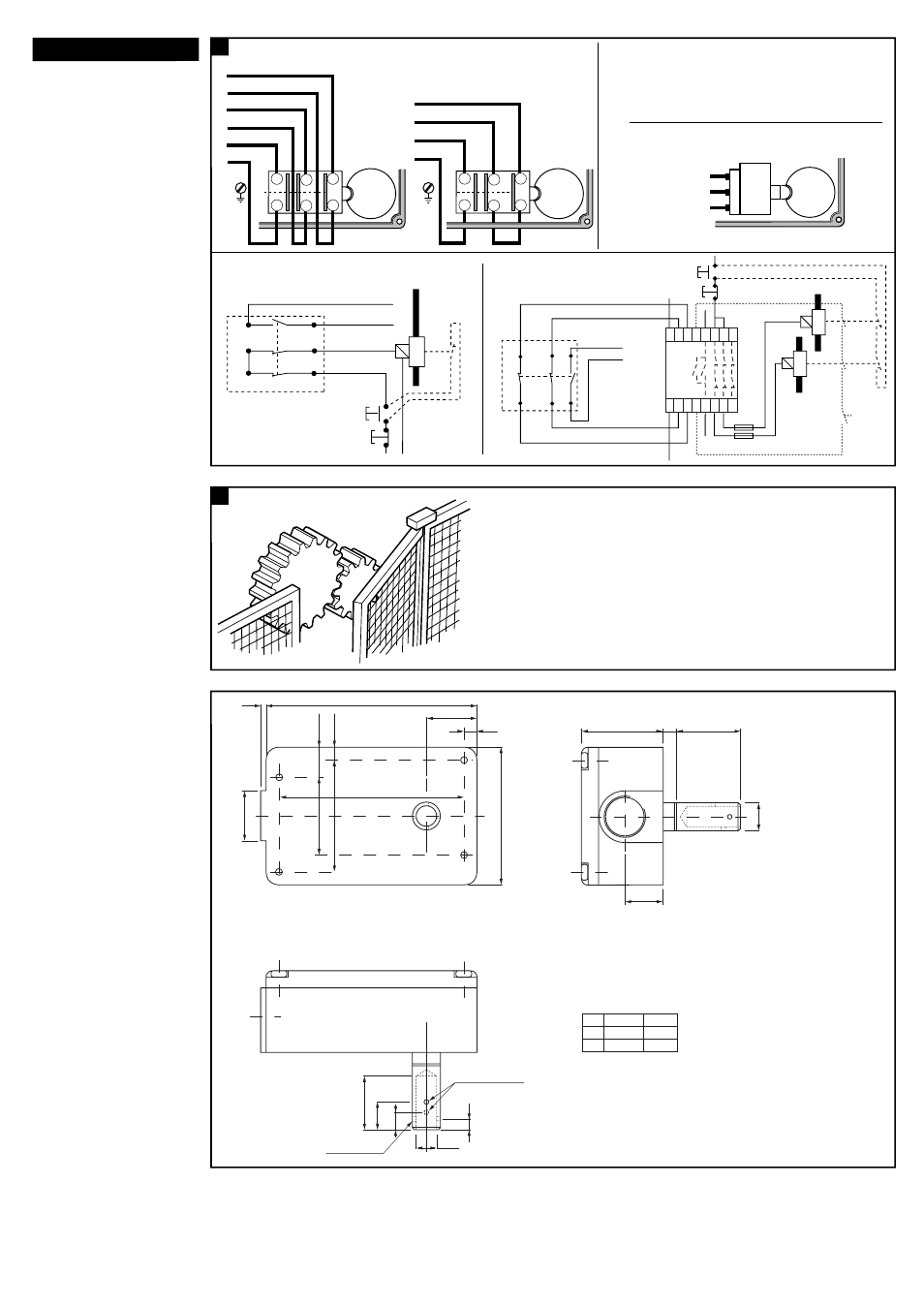
External Connection Examples
(d1)
Pneumatic external Connections
(w)
EX external Connections
(h1)
Application circuit examples
(Shown with machine running)
(s)
Safety circuit 1
(v)
Run Condition.
(s)
Safety circuit 1
(t)
Safety circuit 2
(u)
Auxiliary
(u)
Auxiliary
11
21
33
22
12
34
11
21
22
12
33
34
2
3
1
(a1)
EX Rotacam 2N/C contacts
(b1)
Blue / Brown = Safety circuit 1
(c1)
Black / Black = Safety circuit 2
34
22
12
33
21
11
(i1)
Indication
Circuit
(j1)
Start
(p1)
RESET
momentary
push button
(n)
Fuses
K1
K2
(m1)
Minotaur
monitoring
safety relay
Rotacam
Rotacam
(k1)
Stop
(s)
Safety Circuit 1
(t)
Safety Circuit 2
A1 S13 S23
33
X1 41 13 23
A2 S14 S24
34
X2 42 14 24
(q1)
After wiring replace the lid and check the operation of the interlock system. The guarding system should be
subjected to routine inspection to ensure that the conditions referred to in these instructions are maintained.
Nach Verdrahten Deckel wieder aufsetzen und Funktion überprüfen. Das System ist regelmäßig zu überprüfen,
um die Einhaltung der in dieser Anleitung angegebenen Bedingungen sicherzustellen.
Après câblage, remettre en place le capot et contrôler le bon fonctionnement du système d'interverrouillage.
Le système de protection doit faire l'objet d'une vérification périodique pour s'assurer que le fonctionnement
initial soit maintenu dans le temps.
Type
HS-2
P85
(v1)
SHAFT TYPES
L = Length
30
85
D = DIA
16
12.7
99.0
3.5
23.5
6.5
86.0
A
A
65.0
36.0
24.0
52.0
14.5
6.5
13.0
25.0
5.0
Ø 9.5
(u1)
2 x holes Ø 3.2
(t1)
2 x holes M4
(s1)
Note: Holes only on HS-2
(r1)
Note: This is viewed from underside
Optional: Holes "A" can be tapped M5 from rear.
8.0
D
15.5
38.0
L
6.5
(r)
Verdrahtungsbeispiel.
Exemples de connrxions externes.
(s)
Öffner 1 / Circuit de sécurite 1.
(t)
Öffner 2 / Circuit de sécurite 2.
(u)
Schließer / Contact auxiliaire.
(v)
Maschine läuft.
conditions de fonctionnement.
(w)
Anschlüsse bei EX-Version /Connexions EX
(x)
Rotacam-EX 1Ö + 1S.
Rotacam EX contacts 1N/C + 1N/O.
(y)
Blau/braun = Öffner (not Blue).
Bleu/marron = Circuit de sécurité 1.
(z)
Schwarz/schwarz = Schließer.
Noir/noir = Circuit Auxiliaire.
(a1)
Rotacam-EX 2Ö.
Rotacam EX 2N/C.
(b1)
Blue/braun = Öffner.
Bleu/marron = Circuit de sécurité 1.
(c1)
Schwarz/schwarz = Öffner 2.
Noir/noir = Circuit de sécurité 2.
(d1)
Anschlüsse bei Pneumatic-Version.
Connexions pneumatiques.
(e1)
Ausgang /Commun.
(f1)
Öffner 1 (Durchgang) /N/C (passant).
(g1)
Schließer (kein Durchgang)
N/O (non-passant).
(h1)
Anschlußbeispiele (gezeigt bei laufender
Maschine).
Exemples d'application (présentées
machines tournantes).
(i1)
Anzeigekreis /Présentation des circuits.
(j1)
Start /Marche.
(k1)
Stop /Arrêt.
(m1)
Relais-Sicherheitsbaustein Minotaur.
Relais de sécurité Minotaur.
(n1)
Sicherungen /Fusibles.
(p1)
Reset Taster.
Réarmement par bouton poussoir.
(r1)
Anmerkung: von unten gesehen.
Option: Löcher A können von unten
geschnitten werden.
Note: Vue du dessous.
Option: Les trous « A » peuvent recevoir
des vis M5 par l'arrière.
(s1)
Anmerkung: Löcher nur bei ROTACAM 2.
Note: trous seulement sur HS2.
(t1)
2 Löcher M4 /2 trous pour M4.
(u1)
2 Löcher Ø 3.2 mm /2 trous pour diam 3.2.
(v1)
Wellentypen / Types d'axes.