Troubleshooting, Wiring diagram – Rockwell Automation 193-EIMD60 E3 Overload Relay AC Input Interface Module User Manual
Page 3
Troubleshooting
Failure
Type
Failure
Description
Corrective Action
Input 1..4
1. Input 1,2,3 or 4 does not appear to
recognize a contact closure.
1. Check to ensure that the AC input interface module is properly
secured to the E3 overload relay, and that it's finger connections
to the E3 overload relay terminals are securely tightened.
3. Check the supply voltage. (See "Input Specifications")
4. If the applicable contact closes but the E3 Overload Relay Input
does not recognize the closure (LED does not illuminate), check
the continuity and wiring to the connected contact.
5. Check the IN 1,2,3 and 4 status LEDs. If the appropriate LED
does not illuminate, measure the voltage across and current
through the applicable input. Verify they are within the ratings of
the module (See "Input Specifications").
6. If the appropriate Input LED illuminates, but the input status is not
reported properly over the DeviceNet network, check the
programmable controller ladder logic and the I/O mapping.
2. Verify that AC neutral of the input control circuit is properly
connected to one of the AC COM terminals.
3
4
1
2
22-01-1
1621-01
3
1002483
41053-157
OF
N/A
N/A
N/A
REVISION
AUTHORIZATION
DR.
CHKD.
APPD.
DATE
DATE
DATE
E - DOC
LOCATION: MILWAUKEE, WISCONSIN U.S.A.
B-vertical.ai
DWG.
SIZE
SHEET
B
1
2
3
4
5
6
7
8
A
B
C
D
E
F
G
H
REFERENCE
DIMENSIONS APPLY BEFORE
SURFACE TREATMENT
(DIMENSIONS IN INCHES)
TOLERANCES UNLESS
OTHERWISE SPECIFIED
.XX:
.XXX:
ANGLES:
41053
THIS DRAWING IS THE PROPERTY OF
ROCKWELL INTERNATIONAL CORPORATION
OR ITS SUBSIDIARIES AND MAY NOT BE COPIED,
USED OR DISCLOSED FOR ANY PURPOSE
EXCEPT AS AUTHORIZED IN WRITING BY
ROCKWELL INTERNATIONAL CORPORATION
BULLETIN 193 E3 OVERLOAD RELAY
AC INPUT INTERFACE MODULE
INSTRUCTION SHEET
------------
---------
---------
---------
------------
------------
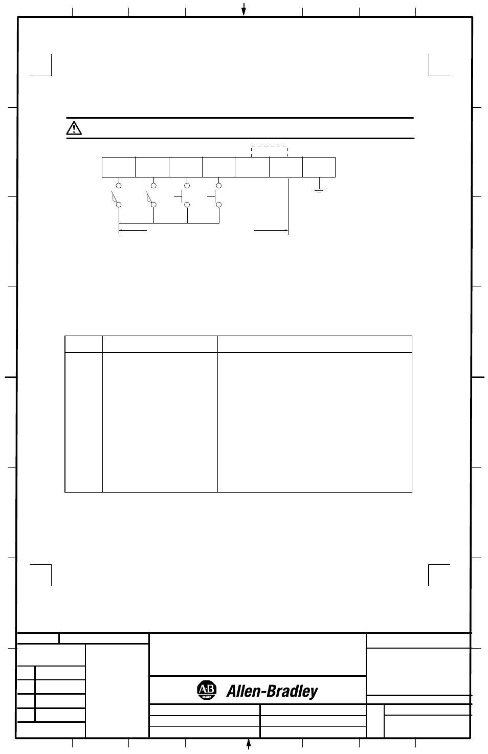
Wiring Diagram
ATTENTION: Be careful when stripping wires. Wire fragments that fall into the module could cause damage at power up. Once
wiring is complete, ensure the module is free of all metal fragments.
Basic wiring of input devices is shown below.
Commons are connected internally.
IN 1
1
2
3
4
5
6
IN 2
IN 3
IN 4
EGND
AC
COM
AC
COM
EIMD = 110/120 V ac 50/60 Hz
EIMD60 = 120 V ac 60 Hz
L1
L2