Rockwell Automation 193-EIMD60 E3 Overload Relay AC Input Interface Module User Manual
Installation instructions dimensions
Bulletin 193-EIMD 110/120V AC 50 / 60 Hz Input Interface Module
Bulletin 193-EIMD60 120V AC 60 Hz Input Interface Module
Installation Instructions
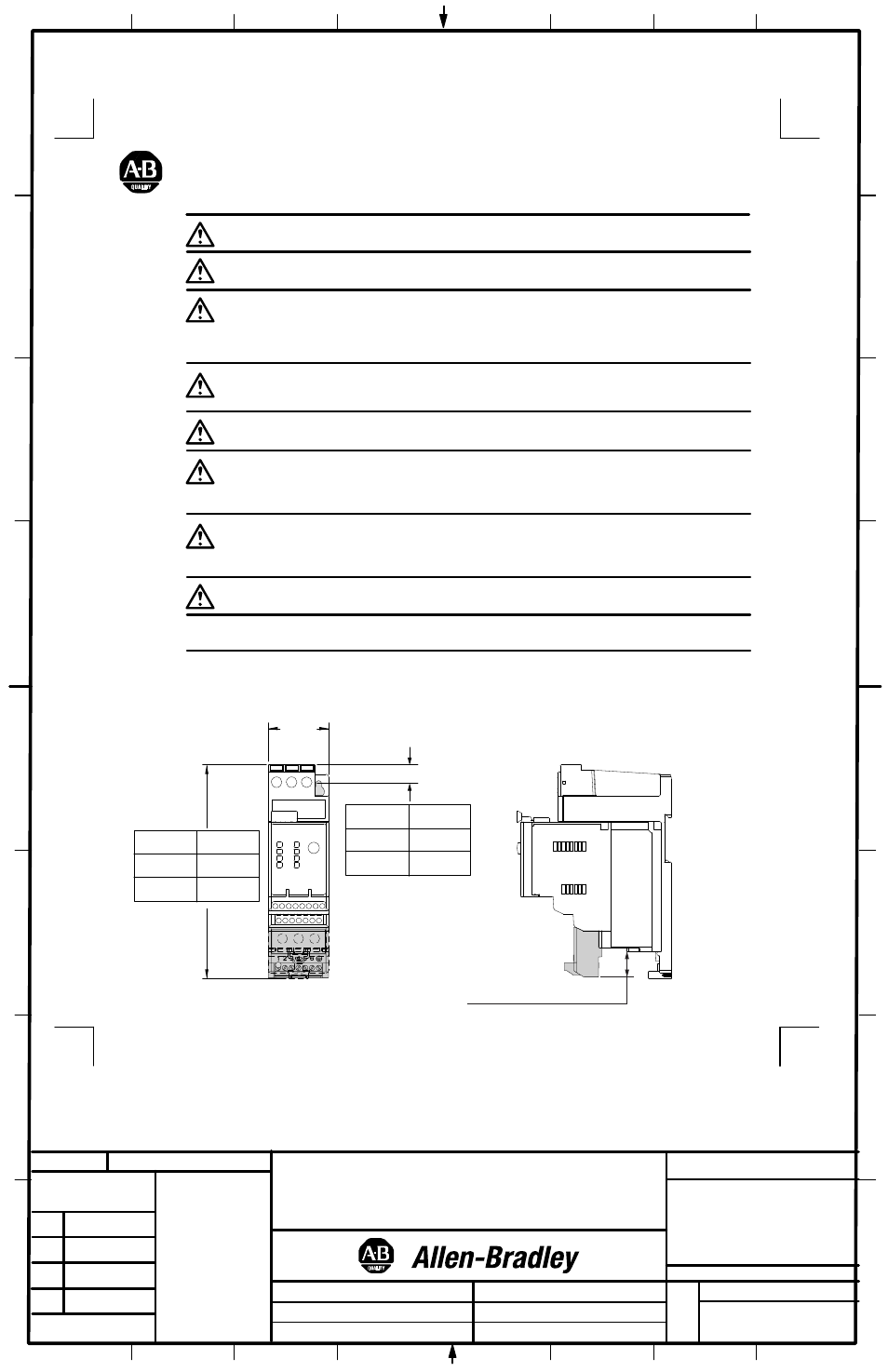
Dimensions
ATTENTION: To prevent electrical shock, disconnect from power source before installing or servicing. Install in
suitable enclosure. Keep free from contaminants.
ATTENTION: The 193-EIMD60 module is designed for applications in 120VAC 60 Hz control circuits only.
ATTENTION: For reliable input signal processing, input wiring shall be routed in raceways separate from power
cabling. For distances exceeding 200 M (656 Ft), the use of shielded cable is recommended.
ATTENTION: The AC input interface module contains ESD (electrostatic discharge)-sensitive parts and assemblies.
Static control precautions are required when installing, testing, servicing, or repairing this assembly. Component
damage may result if ESD control procedures are not followed. If you are not familiar with static control procedures,
refer to Allen-Bradley publication 8200-4.5.2, "Guarding Against Electrostatic Damage", or any other applicable
ESD protection handbook.
ATTENTION: An incorrectly applied or installed AC input interface module can result in damage to the components
or reduction in product life. Wiring or application errors such as supplying incorrect or inadequate supply voltage, or
operating/storing in excessive ambient temperatures may result in malfunction of the AC input interface module.
ATTENTION: Only personnel familiar with the AC input interface module and associated machinery should plan to
install, start up, and maintain the system. Failure to comply may result in personal injury and/or equipment damage.
ATTENTION: The purpose of this document is to serve as a guide for proper installation. The National Electrical
Code and any other governing regional or local code will take precedence. Rockwell Automation cannot assume
responsibility for the compliance or proper installation of the AC input interface module or associated equipment. A
hazard of personal injury and/or equipment damage exists if codes are ignored during installation.
ATTENTION: The AC input interface module is intended to be earth grounded by means of a properly sized wire
(see "Wire Size and Torque Specifications") connecting the EGND terminal to a suitable Earth Ground. Care should
be used to select the shortest possible wire. Failure to ground could result in compromised EMC emissions and/or
immunity.
IMPORTANT: Power cable connections to the E3 Overload relay terminals 2/T1, 4/T2 and 6/T3 must be made
prior to assembling the input interface module to the E3 overload relay.
Approximate dimensions for panel adapter installed units. Dimensions are not intended to be used for manufacturing purposes.
45
(1-25/32)
193-ECPM1
158.5
6 - 1/4"
153.4
6 - 1/32"
155.1
6 - 7/64"
193-ECPM2
193-ECPM3
19.4 (49/64) 193-EC_ _B, 193-EC_ _D
13.2 (33/64) 193-EC_ _E
193-ECPM1
14.1
9/16"
9.0
23/64"
15.5
39/64"
193-ECPM2
193-ECPM3
1
4
1
2
3
22-01-1
1621-01
1002483
41053-157
OF
N/A
N/A
N/A
REVISION
AUTHORIZATION
DR.
CHKD.
APPD.
DATE
DATE
DATE
E - DOC
LOCATION: MILWAUKEE, WISCONSIN U.S.A.
B-vertical.ai
DWG.
SIZE
SHEET
B
1
2
3
4
5
6
7
8
A
B
C
D
E
F
G
H
REFERENCE
DIMENSIONS APPLY BEFORE
SURFACE TREATMENT
(DIMENSIONS IN INCHES)
TOLERANCES UNLESS
OTHERWISE SPECIFIED
.XX:
.XXX:
ANGLES:
41053
THIS DRAWING IS THE PROPERTY OF
ROCKWELL INTERNATIONAL CORPORATION
OR ITS SUBSIDIARIES AND MAY NOT BE COPIED,
USED OR DISCLOSED FOR ANY PURPOSE
EXCEPT AS AUTHORIZED IN WRITING BY
ROCKWELL INTERNATIONAL CORPORATION
BULLETIN 193 E3 OVERLOAD RELAY
AC INPUT INTERFACE MODULE
INSTRUCTION SHEET
C. KACZYNSKI
8-6-03
8-6-03
8-6-03
M. JUTZ
D. BOLDA