Rockwell Automation 44B Installation Instructions User Manual
Page 4
4
Configuring the Sensor
(Background Suppression models)
Once securely installed, the sensing range of the sensor
must be set using the six turn adjustment knob on the top
cover. This knob is used to set the cutoff point (point at which
the background will be suppressed) of the sensor.
1. Apply power to the sensor and ensure that the green
power/stability LED turns ON.
2. Using an instrument screwdriver, adjust the sensor
background cutoff point to its minimum setting by turning
the knob counterclockwise until a “click” can be heard.
The raised dimple on the knob should be at roughly the
11 o’clock position.
3. The background cutoff point for the 44BSB sensor may
be set between 30mm and 300mm.
4. Set the background cutoff point by rotating the knob
clockwise until the orange status LED turns ON (OFF for
44BSB--1KBA1--D4 models).
5. Rotate the background cutoff point knob
counterclockwise until the orange status LED just turns
OFF (ON for 44BSB--1KBA1--D4 models).
6. This indicates that the background has been sensed and
is being suppressed by the sensor. If the indicator does
not turn ON, it means that the background is beyond the
background cutoff point and will be ignored.
7. The sensor is now configured to detect targets between
30mm and this cutoff point. Note that the reflectivity of the
target will influence the distance between the background
and the cutoff point. As illustrated in the figure below, a
nonreflective target will require a greater gap due to the
smaller amount of light being returned to the sensor. Use
the enclosed response curves to help determine the
distance of this gap.
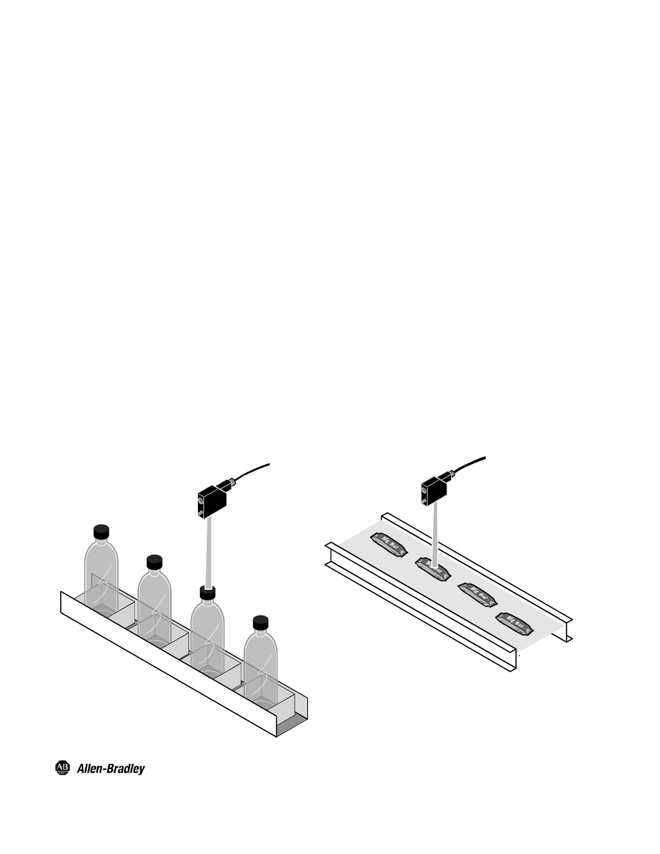
Application Example
Configuring the Sensor
(Foreground Suppression models)
Once securely installed, the sensing range of the sensor
must be set using the six turn adjustment knob on the top
cover. This knob is used to set the cutoff point (point at which
the foreground will be suppressed) of the sensor.
1. Apply power to the sensor and ensure that the green
power/stability LED turns ON.
2. Using an instrument screwdriver, adjust the sensor
foreground cutoff point to its minimum setting by turning
the knob counterclockwise until a “click” can be heard.
The raised dimple on the knob should be at roughly the
11 o’clock position.
3. The foreground cutoff point for the 44BSB sensor may be
set between 30mm and 150mm.
4. Set the foreground cutoff point by rotating the knob
clockwise until the orange status LED turns ON (OFF for
44BSB--1KBA1--D4 models).
5. Continue rotating the knob clockwise until the orange
status LED turns OFF (ON for 44BSB--1KBA1--D4
models).
6. Rotate the foreground cutoff point knob counterclockwise
until the orange status LED just turns ON (OFF for
44BSN--1KBA1--D4 models).
7. This indicates that the background has been sensed and
is being used as the target. When an object is placed
between the sensor lens and this point, it will be detected
due to the absence of reflected light.
8. As with the background suppression sensing modes, the
reflectivity of the target will influence the gap between the
target and the cutoff point. Use the enclosed response
curves to help determine the distance of this gap.
Application Example
Publication 75051--037--01(A)
December 2004
Printed in USA
PHOTOSWITCHR is a registered trademark of Rockwell Automation.
NorylR is a registered trademark of General Electric Company.