Rockwell Automation 44B Installation Instructions User Manual
Rockwell Automation Equipment
1
Installation Instructions
PHOTOSWITCHr Bulletin 44B Photoelectric Sensor
IMPORTANT: SAVE THESE INSTRUCTIONS FOR FUTURE USE.
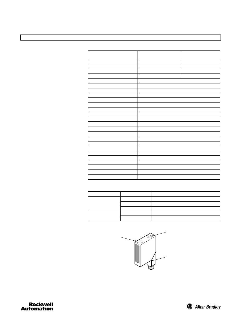
Green
Catalog Number
Sensing Modes
Sensing Range
Light Source
Spot Size
Adjustment Knob
Unit Protection
Supply Voltage
Current Consumption
Maximum Leakage Current
Output Type
Output Mode
Output Rating
Response Time
Housing Material
Lens Material
LED Indicators
Connection Types
Supplied Accessories
Optional Accessories
Operating Environment
Vibration
Shock
Operating Temperature
Relative Humidity
Approvals
44BSB- 1JBA1- D4
44BSB- 1KBA1- D4
Background suppression (BGS)
30 to 300mm
880nm Infrared
20mm spot @ 300mm
6 turn to set cutoff point
Output short circuit, reverse polarity, overload, false pulse
20--30V DC
20mA maximum
10A
NPN and PNP
Light/dark operate by catalog number
100mA @ 24V DC
1ms maximum
High impact acrylic
High impact acrylic
See User Interface table below
4-pin DC micro on 90_ degree swivel
None
Cordsets, mounting brackets
NEMA 3, 4X, 6P, 12, 13 (IP67)
10--55Hz, 1mm amplitude, Meets or exceeds IEC 947--5--2
30G with 1ms pulse duration, Meets or exceeds IEC 947--5--2
--20_C to +70_C (--4_F to +158_F)
595%
UL listed, c--UL, CE marked for all applicable directives
44BSN- 1JBA1- D4
44BSN- 1KBA1- D4
Foreground suppression (FGS)
30 to 200mm
15mm spot @ 200mm
Description
The Bulletin 44B photoelectric sensor
is intended for industrial applications
which require the reliable detection of
objects that fall close to a surface
which must be ignored. Unlike
standard diffuse style sensors, the
Bulletin 44B incorporates a dual
receiver optical system to actively “see”
both the target and the background
areas. This allows the sensor to
suppress any background reflections.
The Bulletin 44B photoelectric sensor
is available in two sensing modes with
a common mechanical optics system.
The difference between the two lies in
their operation. As shown to the right,
both sensing modes will actively “see”
the background condition using the
second internal receiver. The
background suppression sensing
mode will output when it “sees”
reflected light from the target. In
contrast, the foreground suppression
sensing mode will use the background
as a “reflector” and output when
sensed area is blocked by the target.
In general, the foreground suppression
sensing mode should be used when
looking at a dark, irregularly shaped
target on a highly reflective
background. Background suppression
sensing mode is well suited for light
targets on a less reflective background.
For added installation and
troubleshooting assistance, both
sensing modes contain a green LED
status indicator to warn the user of an
unstable application condition, i.e. dirty
lens, low contrast. This indicator will
remain steady ON during normal
operation, but flash to indicate a
change in the application environment.
Features
S
Adjustable background and
foreground suppression models
S
Power, output, and stability status
indicators
S
Micro QD connection with 90_
swivel
S
Low voltage 24V DC operation
S
Protected from miswiring
S
Dual NPN and PNP outputs
S
Fast 1ms response time
General Specifications
Orange
State
OFF
ON
Flashing
OFF
ON
Status
Sensor not powered, output active, SCP active
Sensor powered
Unstable margin
Output not activated
Output activated
Color
Adjustable
Knob
Micro QD
Swivel
LED Status
Indicators
User Interface