Rockwell Automation 44B Installation Instructions User Manual
Page 3
3
Mounting the Sensor
The Bulletin 44B photoelectric sensor must be mounted on a
firm stable surface or support. A mounting which is subject to
excessive vibration or shifting may cause intermittent
operation of the sensor. Rockwell Automation offers a wide
variety of mounting brackets and quick-disconnect cables for
ease of installation. Refer to www.ab.com/sensors for a
complete listing of these products. Once securely mounted,
the sensor can be wired per the attached wiring diagrams.
Wiring the Sensor
The Bulletin 44B photoelectric sensor is available with a
micro quick-disconnect for ease of installation and
maintenance. Rockwell Automation recommends the use of
the 889 Series of cordsets and patchcords. All external
wiring should conform to the National Electric Code and/or all
applicable local codes.
Application Notes
Due to the detection method used by these sensors, it is
important that the sensor be mounted in such a way as to
ensure that the target passes in an orientation perpendicular
to the sensors lenses.
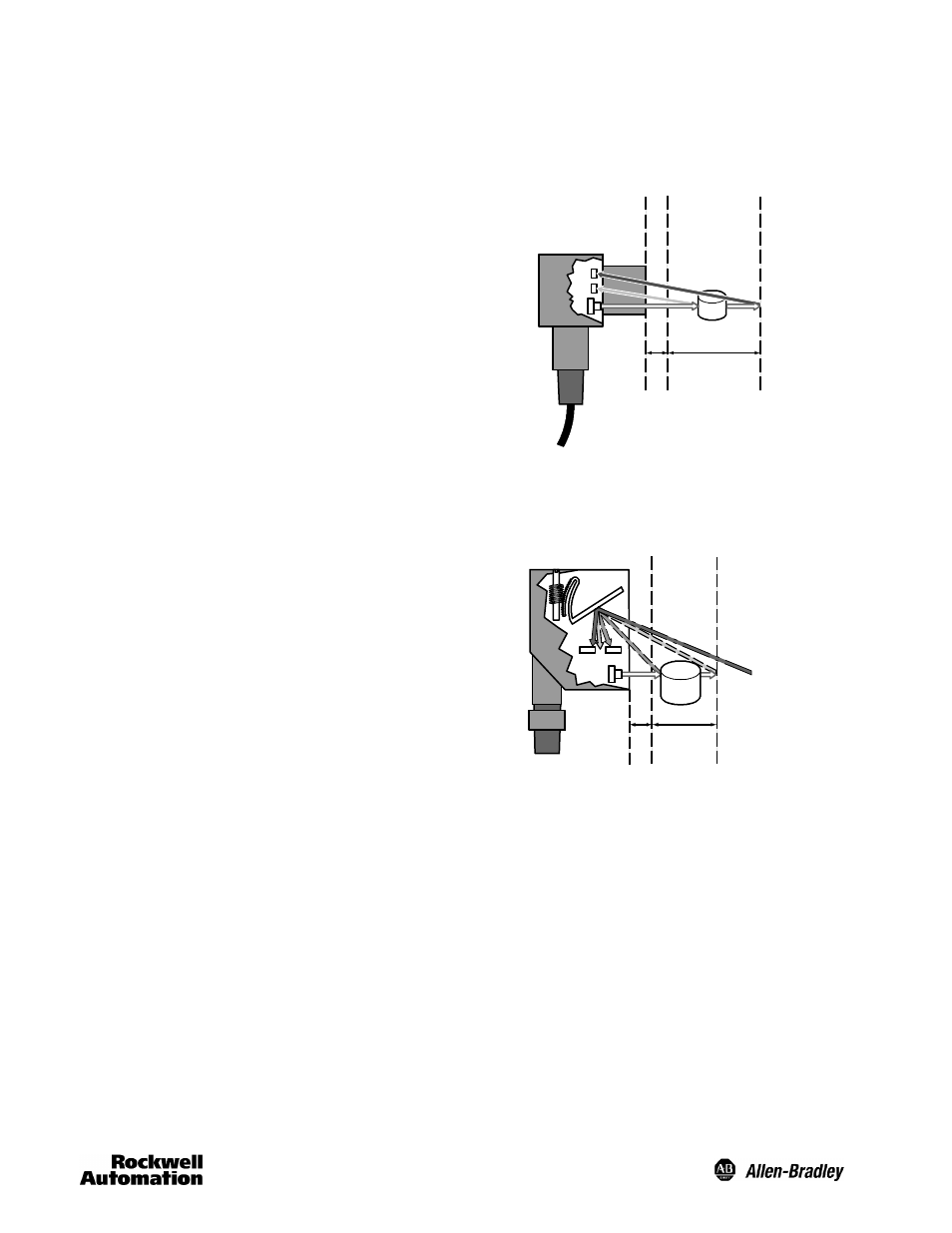
Cutoff
Fixed Sensing
Range
Min
Target
R1
R2
E1
Example of Fixed Background Suppression
The gap between the target and background will vary with
the shape and reflectivity of the target. This variance is
known as the suppression quality and can be determined by
the response curves shown for the sensor.
Cutoff
Adjustable
Sensing Range
Min
Target
R1
R2
E1
R1 = Far
R2 = Near
R2 > R1:out = on
Example of Adjustable Background Suppression