Sensor wiring diagrams, Sensor dimensions—mm (inches), Dc sensors – Rockwell Automation 42KL MiniSight User Manual
Page 4: Ac/dc sensors
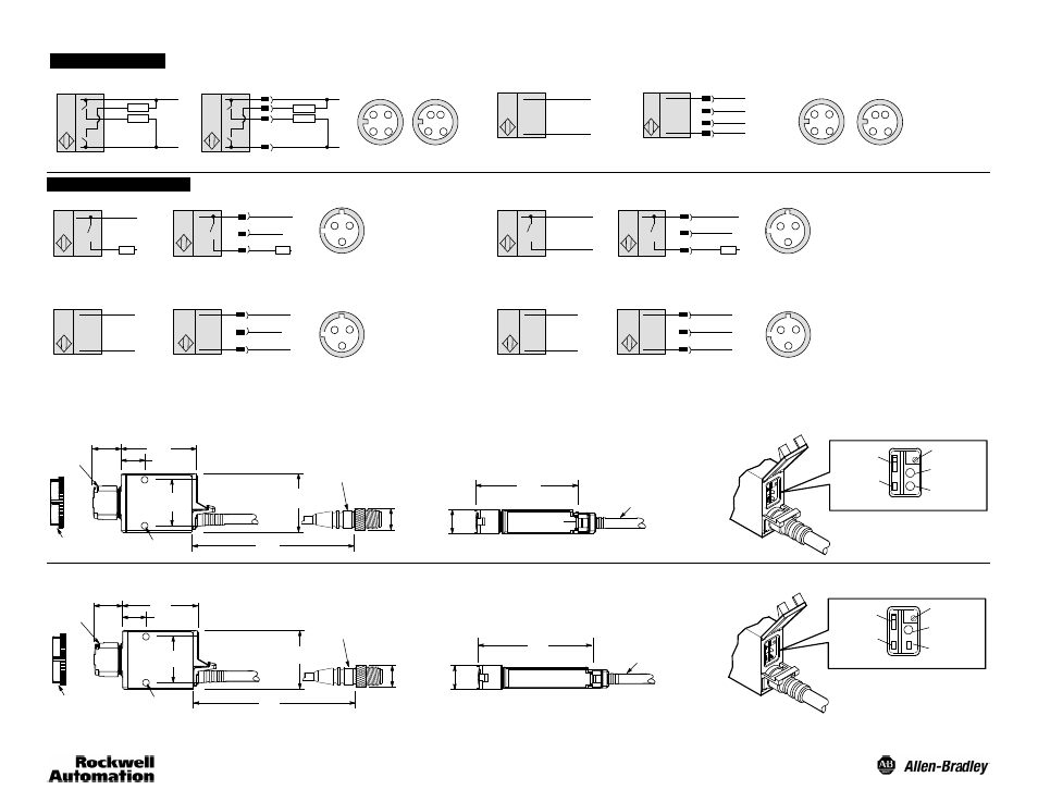
Sensor Wiring Diagrams
Black
NPN/PNP
Brown
Blue
White
Black
+
--
+
--
1
2
4
3
Cable
11--30V DC Sensors
Brown
White
Blue
1
3
2
4
1
3
2 4
Micro
Pico
Brown
Blue
+
--
1
3
+
--
T
T
Cable
Brown
Blue
1
3
2
4
4
2
Transmitted Beam Source
Micro
Pico
~
3
2
1
Brown
Blue
~
~
1
2
3
~
AC Wiring
Cable
22--250V AC/DC Sensors
Red/Black
Red/White
L1
L2
L1
L2
Green
Brown
Blue
+
--
1
2
3
+
--
DC Wiring
Cable
Red/White
Red/Black
Green
3
2
1
Brown
Blue
3
2
T
AC Wiring
Cable
Red/White
Red/Black
Transmitted Beam Source
T
~
~
L1
L2
~
~
L1
L2
1
Green
3
2
1
+
+
--
DC Wiring
Brown
Blue
3
2
--
T
T
Cable
Red/White
Red/Black
1
Green
3
2
1
1
3
2 4
Load
Load
Load
Load
Load
Load
Load
Sensor Dimensions—mm (inches)
DC Sensors
12.7
(0.49)
18 (0.71) Dia.
M18 x 1mm
thread
30.7
(1.21)
24.1
(0.95)
3.5 (0.13)
Dia. Thru for #4 screw
39.6
(1.56)
15
(0.60)
12.2 (0.48)
18mm Mounting Nut
(supplied with sensor)
10in/lbs max torque
152.4
(6)
4-pin Micro Style
Quick Disconnect
14.48
(0.57)
2m (6.56ft) 4-conductor cable
Sensitivity
Adjustment
Power Indicator
(Green)
Output Indicator
(Yellow)
Margin/Short
Circuit Indicator
(Orange)
Light/Dark
Operate Switch
62.6
(2.46)
AC/DC Sensors
Sensitivity
Adjustment
Power Indicator
(Green)
Output Indicator
(Yellow)
Margin/Short
Circuit Indicator
(Orange)
Light/Dark
Operate Switch
12.7
(0.49)
2m (6.56ft) 2-conductor cable
75.3
(2.96)
18 (0.71) Dia.
M18 x 1mm
thread
30.7
(1.21)
24.1
(0.95)
3.5 (0.13)
Dia. Thru for #4 screw
52.3
(2.06)
15
(0.60)
12.2 (0.48)
18mm Mounting Nut
(supplied with sensor)
10in/lbs max torque
152.4
(6)
3-pin Micro Style
Quick Disconnect
14.48
(0.57)
Note: All sensors supplied with an 18mm mounting nut (catalog number 75012--097) except fiber optic sensors 42KL--G1xxx and 42KL--L2xxx. They will use an 18mm mounting nut (catalog number 75012--025).