Rockwell Automation 45BPD Analog Laser Sensor User Manual
Page 8
8
Note: If the target is in the same position when setting both limits of the switching window, a minimum switching
window of 1% of the operating range will be set around the teach point.
Step 2—Scaling the Analog Output Q
A
Press the
X
button until the “Q
A
” LED turns ON indicating that this function can be set.
Position the target at the desired 0% point (4mA).
Press the SET button and the status indicator LED will begin to blink. This sets the 0% setpoint.
Position the target at the desired 100% point (20mA).
Press the SET button and the status indicator LED will turn on as long as SET is pressed to confirm.
This sets the 100% setpoint.
Press the
X
button to advance to the next setting or press the SET and
X
and buttons simultaneously for 1
second to exit the Teach-In process.
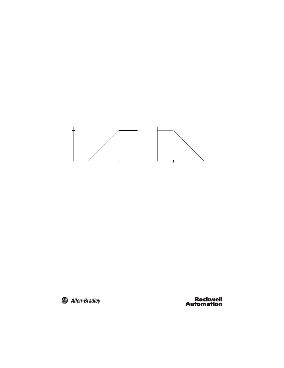
Analog Output
Note: If the distance between the 0% and 100% setpoints is less than 5% of the overall operating range, then the
analog output will be automatically scaled to 5% of the operating range and the middle is placed between
the 0% and 100% setpoints.
Step 3—Setting the Averaging Mode/ Speed Mode
Press the
X
button until the “Av” LED turns on indicating that this function can be set.
This function can be set to either Averaging mode or Speed mode by pressing the SET button.
The status indicator LED will turn on when the Averaging mode is active, the status indicator LED will turn off
when operating in the Speed mode.
Press the
X
button to advance to the next setting or press the SET and
X
and buttons simultaneously for 1
second to exit the Teach-In process.
Note: The averaging mode should be used when detecting rough surfaces. The speed mode should be used when
the shortest response time and maximum switching frequency is required.
20
4
0% Set Point
100% Set Point
Target position
20
4
0% Set Point
100% Set Point
Target position
Analog Cur
re
nt (mA)
Analog Cur
re
nt (mA)