Mounting, Wiring, Possible settings and operating modes – Rockwell Automation 45BPD Analog Laser Sensor User Manual
Page 5
5
Mounting
Securely mount the sensor on a firm, stable surface or support for reliable operation. A mounting which is
subjected to excessive vibration or shifting may cause intermittent operation. The following mounting brackets are
available for installation convenience and sensor protection. Once securely mounted, the sensor can be wired per
the attached wiring diagrams.
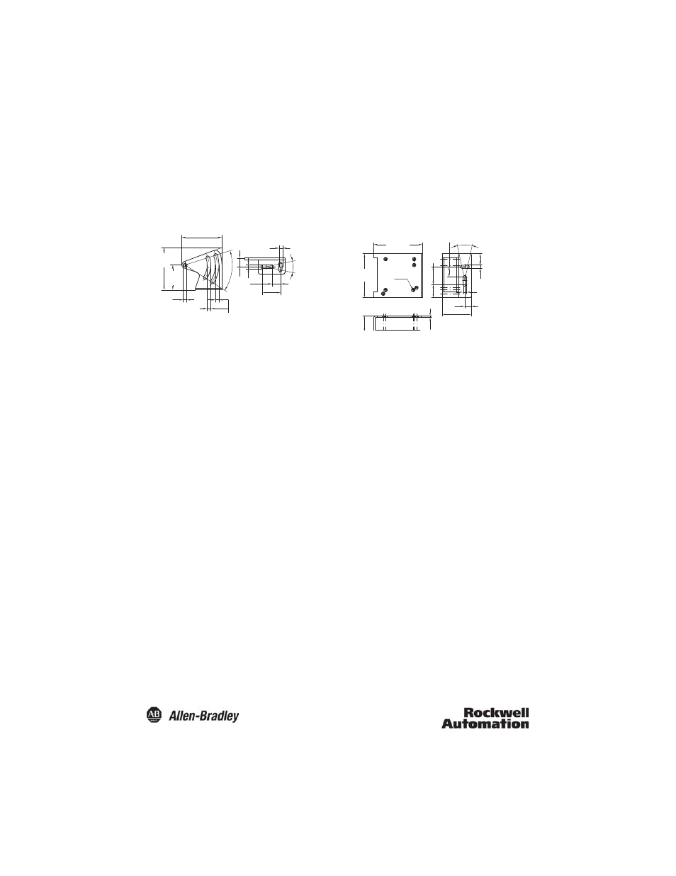
Mounting Bracket Dimensions—mm (in)
45BPD-BKT1
45BPD-BKT2
Wiring
The 45BPD photoelectric sensor is available with a micro quick-disconnect for ease of installation and
maintenance. The connector can be rotated up to 270º to accommodate the installation of the sensor and its
associated wiring. Rockwell Automation recommends the use of the 889 Series of cordsets and patchcords for
quick disconnect model sensors. All external wiring should conform to the National Electric Code and all
applicable local codes.
The 45BPD sensor is ready to operate with factory settings after applying power.
Possible Settings and Operating Modes
•
Set a switching point
•
Set a switching window
•
Scale the analog output between two setpoints (positive or negative slope)
•
Set the operating mode to either Speed mode or Averaging mode
•
Set the switch type (N.O. or N.C.)
•
Reset the sensor to the factory settings
•
Laser disable control (requires electrical connection)
•
Hold the measured value (requires electrical connection)
•
Teach-In button lockout (requires electrical connection)
48.5 (1.9)
4.3 (0.169)
4.2
(0.165)
10.5 (0.41)
22 (0.86)
24˚
4.3 (0.169)
10.5
(0.41)
50˚
30
(1.18)
50.97
(2.0)
4.3
(0.169)
21.2
(0.83)
13.9
(0.54)
58
(2.28)
4.3
(0.169)
24˚
4.3 (0.169)
14.85 (0.58)
17
(0.66)
23.8
(0.93)
7 x M4
38.2 (1.5)
8.5
(0.33)
65 (2.55)