Rockwell Automation 45FSL General Purpose Fiber Optic Sensors User Manual
Page 3
3
Light/Dark Operate Switch
LIGHT or DARK operation modes may be chosen by
changing mode switch.
4/8 Channel Cross-Talk Protection
The 45FSL is equipped to prevent cross-talk to up to 4
ganged sensors providing a 250
µ
s response time or up to 8
ganged sensors maintaining a 500
µ
s response time. Each
sensor communicates through 2 small optic windows that
transmit and receive coded signals (see below).
Receiver
Transmitter
Ganging up to 4 Sensors on DIN Rail
S
Mount and align up to 4 sensors on DIN rail
S
Move cross-talk selector switch to “4” on all sensors.
(Sensors will not function if cross-talk selector switch is set
to “8” on any sensor.)
S
Install fiber optic cables
S
Power up sensor
1 2
3 4
1 2
3 4
Ganging 4 to 8 Sensors on DIN Rail
S
Mount and align up to 8 sensors on DIN rail.
S
Move cross-talk selector switch to “8” on all sensors.
(Sensors will not function if cross-talk selector switch is set
to “4” on any sensor.)
S
Install fiber optic cables
S
Power up sensor
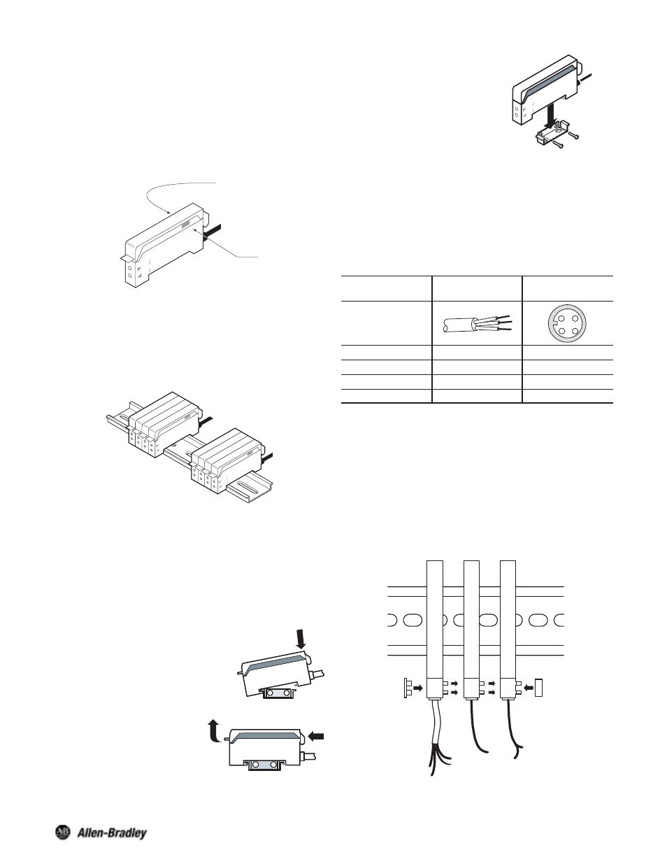
Mounting the Sensor
How to Attach Sensor to DIN Rail
Attach front hook of the photoelectric
sensor onto rail (or mounting bracket)
and press rear end of sensor down
until unit snaps into place.
How to Detach Sensor from DIN Rail
Pushing the sensor unit forward,
pull up on the front of the sensor
until the front hook is detached.
Remove sensor.
Л
К
Side Mounting Sensor with Bracket
Fasten mounting bracket assembly
using M3 screws. Tightening torque is
0.8Nm max. Attach front hook of the
photoelectric sensor onto mounting
bracket and press rear end of sensor
down until unit snaps into place.
Л
К
Wiring the Sensor
Choice of Power Bus, 2m (6.5ft) cable, or 4 pin QD connector
are provided for wiring the 45FSL Series sensors. On the pico
QD models Rockwell Automation/Allen-Bradley recommends
the use of the 889 Series cordsets and patchcords (i.e.,
889P–F4AB–2). Standard 2m (6.5ft) cable lengths are
provided with flying leads for hard wiring. Hard wiring color
coding and pin assignment for QD connectors are as specified
below.
Designation
Lead Color
2m (6.5ft) Cable
Pin Assignment
4 Pin Pico QD
Termination
1
4
3
2
V+
Brown
1
0V
Blue
3
Output
Black
4
Stability Output
Orange
2
The Power Bus option utilizes quick disconnect cordsets
which are prewired with up to four conductors. When ganging
sensors (up to 16 units maximum) using the Power Bus
connection system, select either a 4-wire cable (plus/minus
power output and stability output) or a 3-wire cable
(plus/minus power output) for the first control. For the
additional controls in a system, select either a 2-wire cable
(output and stability output) or a 1-wire cable (output only) to
complete the system.
Wiring Diagram/Power Bus Option
Orange
Stability
_
+
_
+
Maximum number of
units paralleled: 16
Female
End Cap
Male
End Cap
Brown
+ V
- V
Blue
Black Output
Black
Output
Black
Output
Orange
Stability