2user interface, Sensor selection, Output and stability indicators – Rockwell Automation 45FSL General Purpose Fiber Optic Sensors User Manual
Page 2: Output timer selector switch, Turn sensitivity adjustment
2
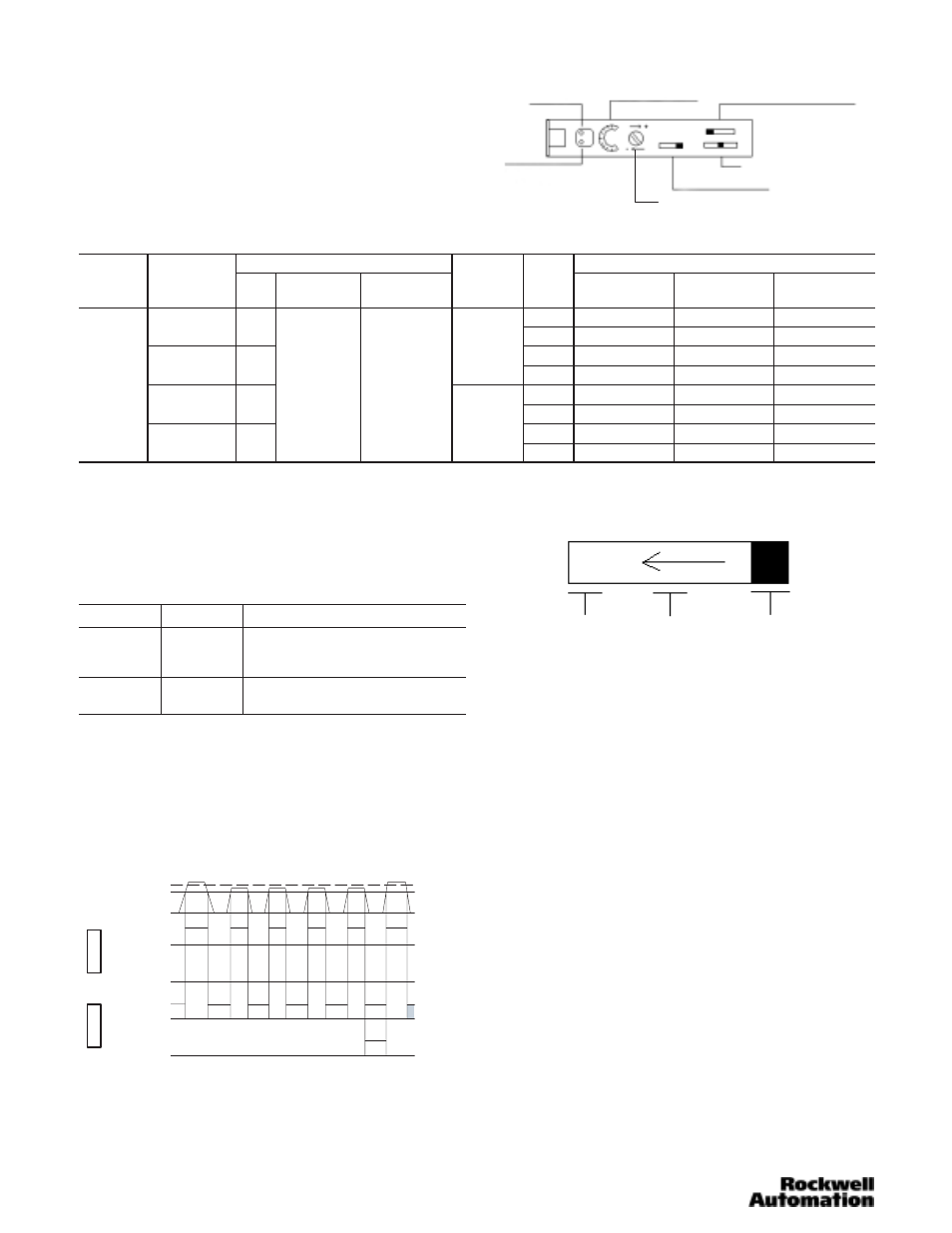
User Interface
The user interface contains a light/dark operate switch, output
timer selector switch, interference protection switch, 8-turn
sensitivity adjustment knob with indication, and output LED
indicators for configuring and viewing the sensor’s operation
and status. A more complete description of each item is
described below.
Stability Indicator
(Green LED)
8ĆTurn Sensitivity Indicator Interference Protection Selector Switch
Output Timer Selector Switch
Light/Dark Operate Switch
Output Indicator
(Orange LED)
8ĆTurn Sensitivity Adjustment
Sensor Selection
Output Characteristics
Catalog Number
Operating
Voltage
Current
Consumption
Type
Max Load
Current
Max Leakage
Current
Response
Time
LED
Cable
Pico
Power Bus
(QD required)
40ma or Less
PNP
Selectable
Red
45FSL-2LHE-A2
45FSL-2LHE-P4
45FSL-2LHE-C4 Ê
40ma or Less
PNP
Selectable
250µs
White
45FSL-5LHE-A2
45FSL-5LHE-P4
45FSL-5LHE-C4 Ê
35ma or Less
NPN
250µs
or
500 s
Red
45FSL-2LGE-A2
45FSL-2LGE-P4
45FSL-2LGE-C4 Ê
12-24V DC
35ma or Less
NPN
Output: 100ma
0 5ma
500µs
White
45FSL-5LGE-A2
45FSL-5LGE-P4
45FSL-5LGE-C4 Ê
12 24V DC
+/- 10%
40ma or Less
PNP
Output: 100ma
Stability: 50ma
0.5ma
Red
45FSL-2LWE-A2
45FSL-2LWE-P4
45FSL-2LWE-C4 Ê
40ma or Less
PNP
30µs
White
45FSL-5LWE-A2
45FSL-5LWE-P4
45FSL-5LWE-C4 Ê
35ma or Less
NPN
30µs
Red
45FSL-2LVE-A2
45FSL-2LVE-P4
45FSL-2LVE-C4 Ê
35ma or Less
NPN
White
45FSL-5LVE-A2
45FSL-5LVE-P4
45FSL-5LVE-C4 К
К
PowerBus master/4 conductor QD = 45F–A4C–A2
PowerBus slave/2 conductor QD = 45F–A2C–A2
Output and Stability Indicators
Two LEDs (green and orange) indicate a variety of conditions
to facilitate set-up and troubleshooting. The function of each is
described in the table below. Relevant output and stability
data are also shown.
LED
State
Condition
Green
OFF
ON
Flashing
Unstable light signal
Stable light signal
4 consecutive unstable light levels
Orange
OFF
ON
Output OFF
Output ON
Stability Output is an output feature provided by the 45FSL
sensor which monitors any changes or reduction of reflected
light levels during operation. Reflected light levels must reach
120% of the threshold required for normal operation to
achieve a “Stability Output.” If the sensor detects light levels
less than 120% of threshold 4 consecutive times then the
green LED starts flashing and remains flashing until a stable
light level is achieved (120%) (see illustration below).
120%
100%
Operating Level
ON
OFF
ON
OFF
ON
OFF
ON
OFF
Normal
Output
Stability
Output
Normal
Output
Stability
Output
Light On
Dark On
Output Timer Selector Switch
OFF D
ON D
NOR
NOR: Provides normal on/off output switching
ON D: Provides output on delay (40ms)
OFF D: Provides output off delay (40ms)
8-Turn Sensitivity Adjustment
An 8-turn sensitivity adjustment (potentiometer) is built into the
sensor’s user interface for accuracy in detecting very small
objects or differentiating between colors.
Diffuse Set Up—Light Operate Mode
With target in position, turn sensitivity adjustment clockwise
until orange LED turns on (point A).
With no target in position the green and orange LEDs should
be off. Otherwise turn the sensitivity adjustment clockwise to
max or until orange LED turns on. If orange LED turns on,
then turn sensitivity adjustment counterclockwise until orange
LED turns off (point B).
Set sensitivity adjustment midway between points A and B.
Confirm sensor operation.
Transmitted Beam Set Up—Dark Operate Mode
With no target present, turn the sensitivity adjustment
clockwise to max until the orange and green LEDs turn on
(point A).
Green/orange LEDs should turn off. Otherwise turn sensitivity
adjustment counterclockwise until the green/orange LEDs turn
off. Turn sensitivity adjustment counterclockwise additional
one quarter turn and confirm sensor operation.