Control wiring, Drive run interlock, Control wiring -8 – Rockwell Automation 20T PowerFlex Diode Bus Supply User Manual
Page 20: Drive run interlock -8
1-8
Installation/Wiring
PowerFlex Diode Bus Supply User Manual
Publication 20T-UM001D-EN-P
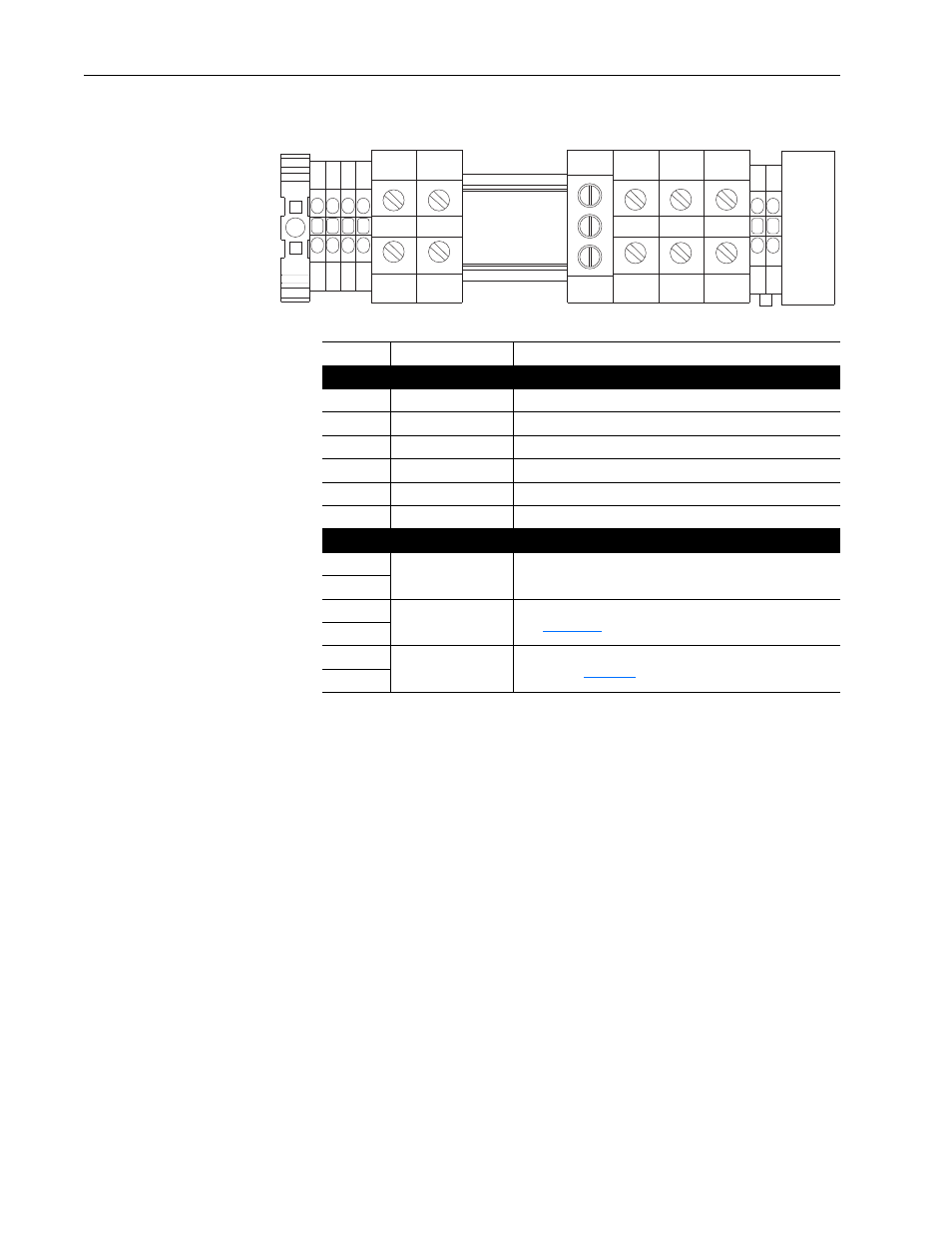
Figure 1.3
Power and Control Terminals
Control Wiring
Important points to remember about control wiring:
• Use Copper wire only. Wire gauge requirements and recommendations
are based on 75 °C (168 °F). Do not reduce wire gauge when using
higher temperature wire.
• Wire with an insulation rating of 600V or greater is recommended.
• Control wires outside the cabinet
should be separated from power wires
by at least 0.3 meters (1 foot).
Drive Run Interlock
To protect the Diode Bus Supply from overtemperature, the normally closed
contacts (Bus Supply Overtemperature - terminals 10 and 11) should be
wired to either the AC line input contactor for the Diode Bus Supply or the
Run interlock circuit (enable input) of each connected drive. This ensures
that the drives are stopped in case of Bus Supply Overtemperature.
PE
8
9
11
10
DC +
DC -
R (L1) S (L2) T (L3)
GND
12
MOV
Terminal
Description
Notes
Power Connections
DC +
DC Bus (+)
DC Bus Connection (+)
DC -
DC Bus (-)
DC Bus Connection (–)
PE
PE Ground
Safety Ground
R
R (L1)
AC Line Input Power
S
S (L2)
AC Line Input Power
T
T (L3)
AC Line Input Power
Control Connections
8
24V Fan Supply
Internal connection to extend fan supply leads
(must be disconnected in case of fan replacement)
9
10
NC Contact Output
(F1, F2)
Opens with power stack overtemperature.
(See
for contact ratings.)
11
12
Jumper
MOVs to Ground
Disconnect MOV neutral point and ground by removing this
jumper. (See
for details.)
GND