Maximum loading, Ac input fusing, Maximum loading -5 ac input fusing -5 – Rockwell Automation 20T PowerFlex Diode Bus Supply User Manual
Page 17
Installation/Wiring
1-5
PowerFlex Diode Bus Supply User Manual
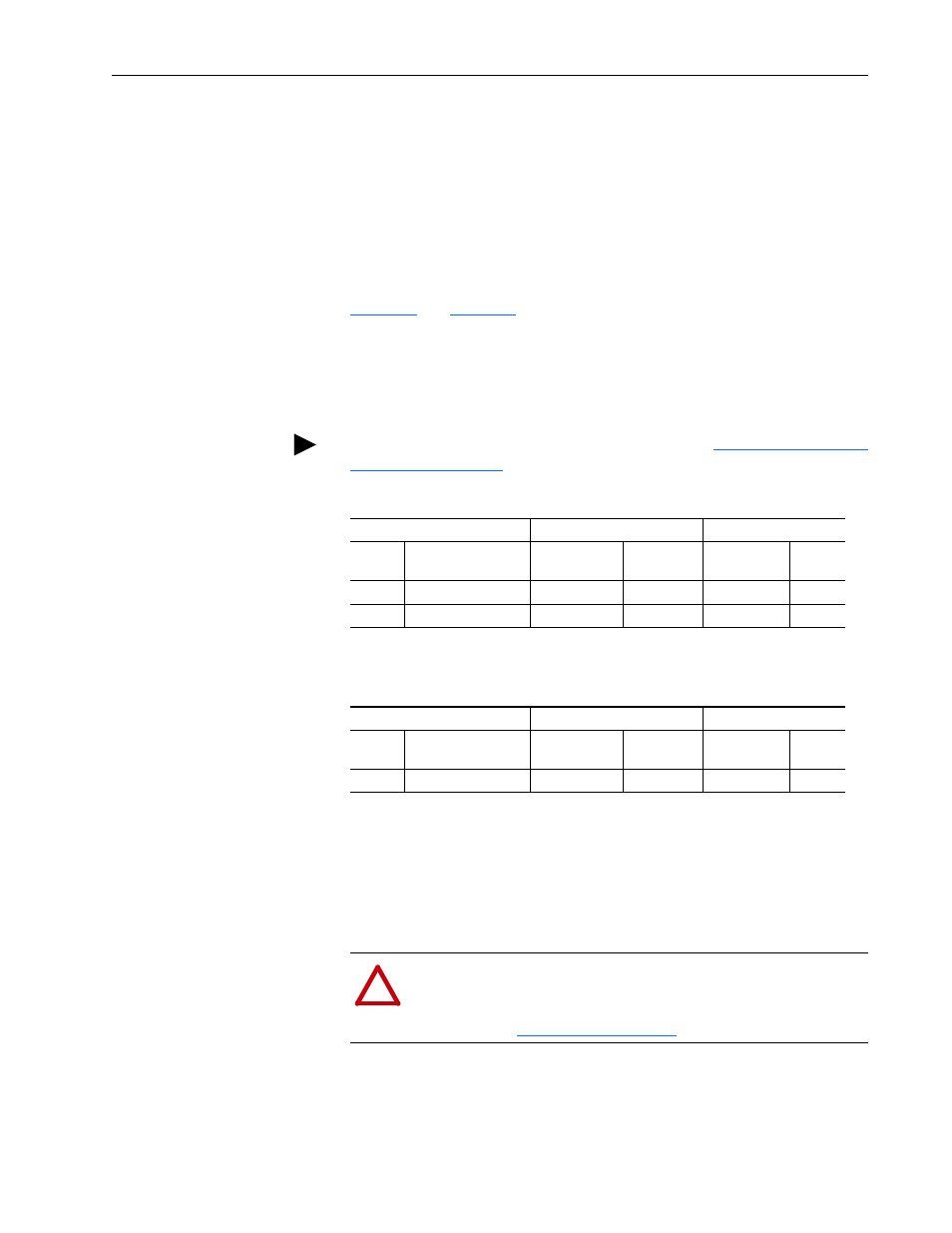
Maximum Loading
To avoid overloading the Diode Bus Supply, the following requirement
applies:
The DC Input current sum (Normal Duty or Heavy Duty rating at 40 °C/
104 °F) of the connected drive(s) must not exceed the Bus Supply
continuous DC Bus output current rating of 120 amps at 40 °C/104 °F.
For the DC Input Current values of the drives, see tables in the respective
drive documentation.
Table 1.A
and
Table 1.B
provide guidance on the nominal operation of the
Diode Bus Supply. No overload capability is built into the tables.
When an overload is being utilized in connected drives or products, that
overload current must be accounted for in the calculation to properly size
the Diode Bus Supply.
Table 1.A Normal Duty ND
Table 1.B Heavy Duty HD
AC Input Fusing
The Diode Bus Supply can be installed with delay type AC input line fuses.
National and local industrial safety regulations and/or electrical codes may
determine additional requirements for these installations.
TIP: When paralleling two Diode Bus Supplies, see
Drive Rating
Drive DC Input Current
Diode Bus Supply
(1)
(1)
No overload capability.
DC
Voltage
ND
Power
ND DC Input
Currents
ND DC Input
Current Sum
Maximum DC
Output Amps
AC Input
Voltage
540V
30 + 22 = 52 kW
61.9 + 47.5
109.4 A
120 A
400V
650V
2 x 40 = 80 Hp
2 x 55.7
111.4 A
120 A
480V
Drive Rating
Drive DC Input Current
Diode Bus Supply
(1)
(1)
No overload capability.
DC
Voltage
HD
Power
HD DC Input
Currents
HD DC Input
Current Sum
Maximum DC
Output Amps
AC Input
Voltage
540V
37 + 2 x 1.5 = 40 kW
95.1 + 2 x 5.3
105.7 A
120 A
400V
!
ATTENTION: The PowerFlex Diode Bus Supply does not
provide branch short circuit protection. Specifications for the
recommended fusing to provide protection against short circuits
are provided in