Mounting, Wiring diagrams – Rockwell Automation 45CLR ColorSight User Manual
Page 2
2
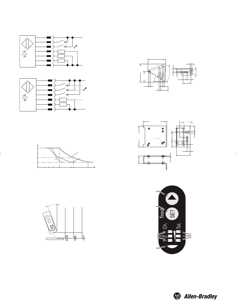
Mounting
Securely mount the sensor on a firm, stable surface or support for
reliable operation. The following mounting brackets are available for
installation convenience and sensor protection. Once securely
mounted, the sensor can be wired per the attached wiring diagrams.
45BPD-BKT1 Approximate Dimensions—mm (in)
Wiring Diagrams
48.5 (1.9)
4.3 (0.169)
4.2
(0.165)
10.5 (0.41)
22 (0.86)
24˚
4.3 (0.169)
10.5
(0.41)
50˚
30
(1.18)
50.97
(2.0)
4.3
(0.169)
2
(0.07)
21.2
(0.83)
13.9
(0.54)
58
(2.28)
4.3
(0.169)
24˚
4.3 (0.169)
14.85 (0.58)
17
(0.66)
23.8
(0.93)
7 x M4
38.2 (1.5)
8.5
(0.33)
65 (2.55)
45BPD-BKT2 (Protective Bracket) Approximate
Dimensions—mm (in)
Teach Interface
Red Tolerance LEDs
► Button
SET Button
Yellow Output Channel LEDs
Green Indicator LED
Remote Teach
+DC
Gnd
2
1
5
6
4
3
7
Gating Input
Q1
Remote Teach
Teach Lock
GY
BN
WH
PK
YE
GN
BU
Teach Confirmation
The control input (pin 5) can be used to lock the ColorSight
pushbuttons by connecting it to the +DC (18…28V DC). When
working with the sensor in remote teach, we recommend the use of
pushbutton lockout to prevent accidental tampering of the
configuration.
Percentage of Color Detection vs. Sensing Range
Sensor Alignment
Position the 45CLR sensor so that the distance from the object to
the sensor will be within the sensing range. Extremely shiny or
reflective surfaces can distort the color detection This sensor should
be mounted at an angle of 10...30°, as shown below.
45CLR-5JPC1-D8
15
30
18
> 20 % Reflective
mm
25
50
75
100
12
22
32
42
%
45CLR-5JPC2-D8
45CLR-5JPC3-D8
12…32 mm 45CLR-5JPC1-D8
10…30°
15…30 mm 45CLR-5JPC2-D8
18…22 mm 45CLR-5JPC3-D8
2
1
5
6
+DC
Gnd
GY
BN
WH
PK
YE
GN
BU
4
3
7
Q3
Q2
Q1
Teach Lock