Rockwell Automation 22-COMM PowerFlex 4-Class DSI (Drive Serial Interface) Network Communication Adapter User Manual
Page 4
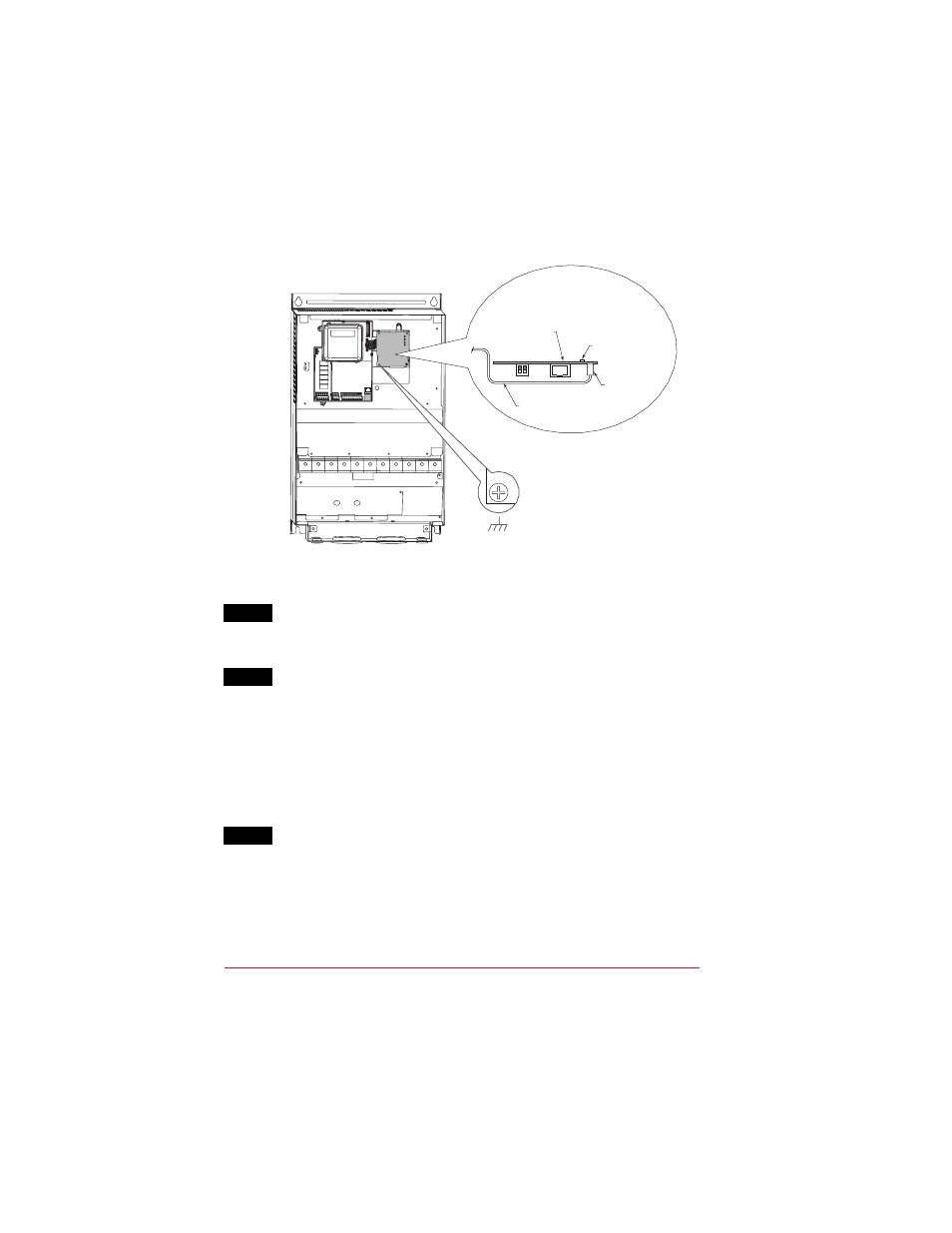
Figure 3 Mounting and Connecting the Adapter – PowerFlex 400 Class Frame D and
Higher
Step 5
Connect one end of the network cable to the network. Make sure to use
the proper cable for the network. See the adapter User Manual’s “Related
Documentation” section for appropriate publication(s).
Step 6
Route the other end of the network cable through the bottom of the
PowerFlex 40/400 Class drive, and connect the cable to the adapter using
the adapter’s mating socket or terminal block. For complete wiring details,
see the adapter User Manual.
Important: Make sure to properly route, wire, and ground the cable.
Always separate the communications wiring from the power
and motor wiring. For more information, see Wiring and
Grounding Guidelines for PWM AC Drives.
Step 7
Read the adapter User Manual for information to configure and
determine how to apply the network to the host product.
PowerFlex 400 Drive (Frame D shown
as example with cover removed)
Adapter Installation
(Side View)
Bottom of
Adapter Board
Internal Interface
Ribbon Cable
Connector
LEDs
0.9 N-m
(8.0 lb.-in.)
1 Place
www.rockwellautomation.com
Americas: Rockwell Automation, 1201 South Second Street, Milwaukee, WI 53204-2496 USA, Tel: (1) 414.382.2000, Fax: (1) 414.382.4444
Europe/Middle East/Africa: Rockwell Automation, Vorstlaan/Boulevard du Souverain 36, 1170 Brussels, Belgium, Tel: (32) 2 663 0600, Fax: (32) 2 663 0640
Asia Pacific: Rockwell Automation, Level 14, Core F, Cyberport 3, 100 Cyberport Road, Hong Kong, Tel: (852) 2887 4788, Fax: (852) 2508 1846
Power, Control and Information Solutions Headquarters
U.S. Allen-Bradley Drives Technical Support
Tel: (1) 262.512.8176, Fax: (1) 262.512.2222, Email: [email protected], Online: www.ab.com/support/abdrives
Publication 22COMM-IN002A-EN-P – January, 2008
P/N 376924-P01
Copyright © 2008 Rockwell Automation, Inc. All rights reserved. Printed in USA.