Rockwell Automation 22-COMM PowerFlex 4-Class DSI (Drive Serial Interface) Network Communication Adapter User Manual
Page 2
2
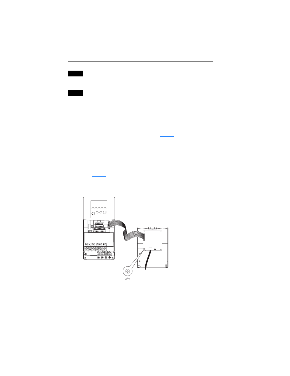
Figure 1 Mounting and Grounding the Adapter – PowerFlex 40 Class Frames B and C,
and PowerFlex 400 Class Frame C
Step 3
If the adapter has address or data rate switches, and/or an Operating
Mode jumper, set them to appropriate positions. See the adapter User
Manual for complete details.
Step 4
Mount the adapter.
PowerFlex 40 Class Frames B and C, and PowerFlex 400 Class Frame C
A. Mount the adapter on the required special drive cover (see
Figure 1
for
part numbers).
–
Frame C: Use the adapter screw to secure the adapter to the cover.
Important: Tighten the adapter’s lower left screw to properly
ground the adapter (see
Figure 1
).
–
Frame B: Disregard the screw and snap the adapter in place.
Important: Install the drive cover onto the drive using both cover
fasteners to properly ground the adapter.
B. Connect one end of the Internal Interface cable to the DSI port on the
drive and the other end to the mating DSI connector on the adapter
(
).
PowerFlex 40 Drive
(Frame C shown as
example with cover removed)
Adapter Mounted on Back of
Required Special Drive Cover
(Frame C cover shown)
PowerFlex 40 Class Frame B: Part No. 22B-CCB
PowerFlex 40 Class Frame C: Part No. 22B-CCC
PowerFlex 400 Class Frame C: Part No. 22C-CCC
Ground for Frame C Drives
NOTE: For Frame B drives, the lower
left adapter screw does not ground the
adapter. To ground the adapter, install
the special drive cover onto the drive
using both cover fasteners.
0.9 N-m
(8.0 lb.-in.)
1 Place