Weidmuller WI-I/O-EX: Wireless I/O Expansion Modules v1.11 User Manual
Page 40
WI-I/O-EX Serial I/O Module
User Manual v1.11
Page 40
February 2010
Digital inputs are reflected in the software by blacking (ON) or greying (OFF) of the
associated label in the Digital Inputs column.
The pulse output count values are also shown. The pulse out target may be set by clicking
the Edit Targets button. Pulses will be produced until the count reaches the target.
The analog inputs can be viewed in decimal or hexadecimal and represents a fraction of
the analog signal, where hex 4000 is 0% and hex C000 is 100%.
In differential configuration, only the value of the first channel in the differential pair
shows the quantity being measured. The second channel of each differential pair should
be ignored.
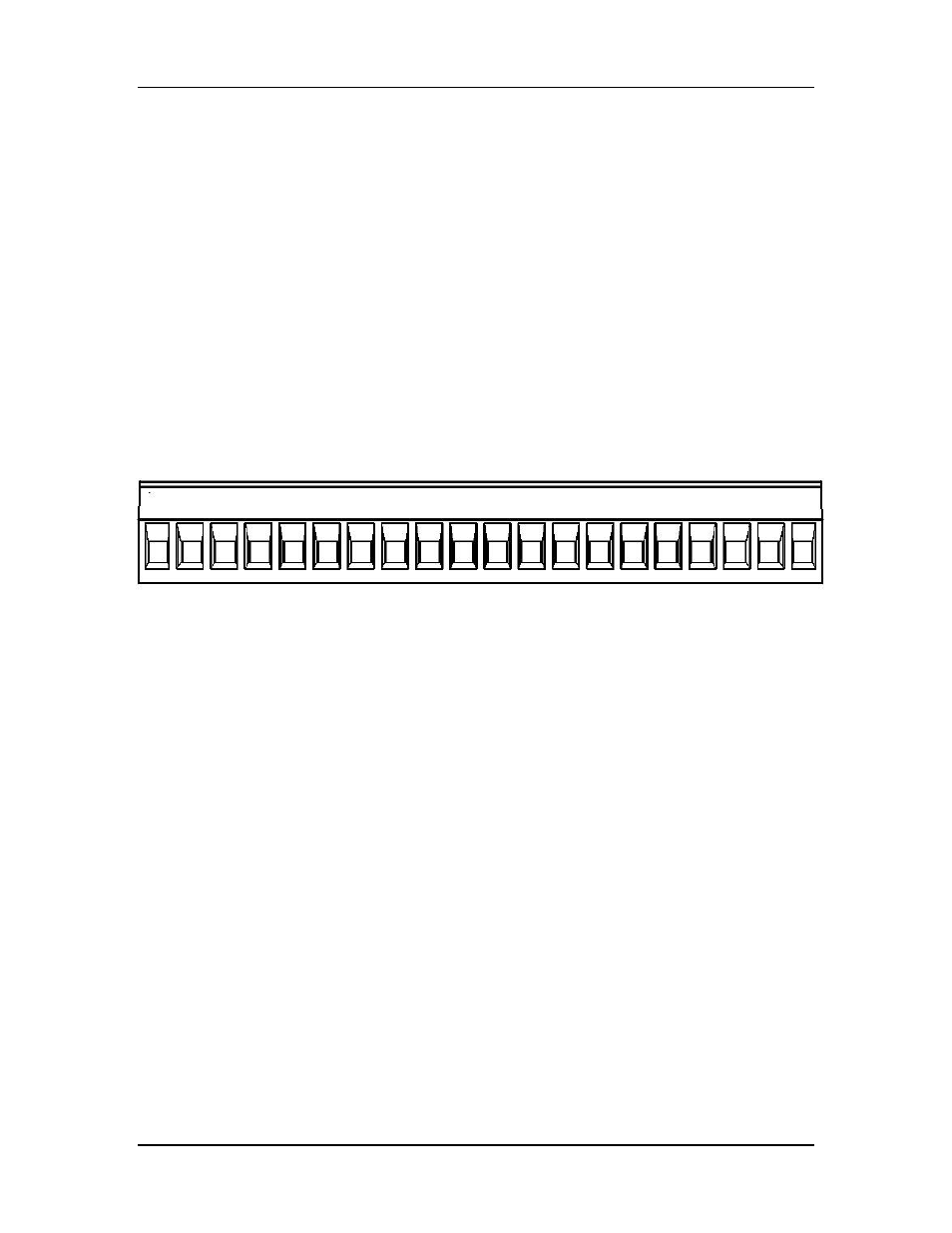
5.3 WI-I/O-EX-1-S-13 module
The I/O terminal block for the WI-I/O-EX-1-S-13 is shown in Figure 5-5.
Figure 5-5: I/O terminal block for WI-I/O-EX-1-S-13.
Pulse outputs coincide with DIO terminals 1-8.
The operation of the WI-I/O-EX-1-S-13 may be confirmed using the configuration
software. Start the software as described in chapter 4, and choose the AOT Check page.
DIO DIO DIO DIO DIO DIO DIO DIO
ALS AOT AOT AOT AOT AOT AOT AOT AOT A ALS
1
2
3
4
5
6
7
8 Earth +24
1
2
3
4
5
6
7
8 GND +24