Weidmuller WI-I/O-EX: Wireless I/O Expansion Modules v1.11 User Manual
Page 13
WI-I/O-EX Serial I/O Module
User Manual v1.11
WI-IO-EX Manual v1.11
Page 13
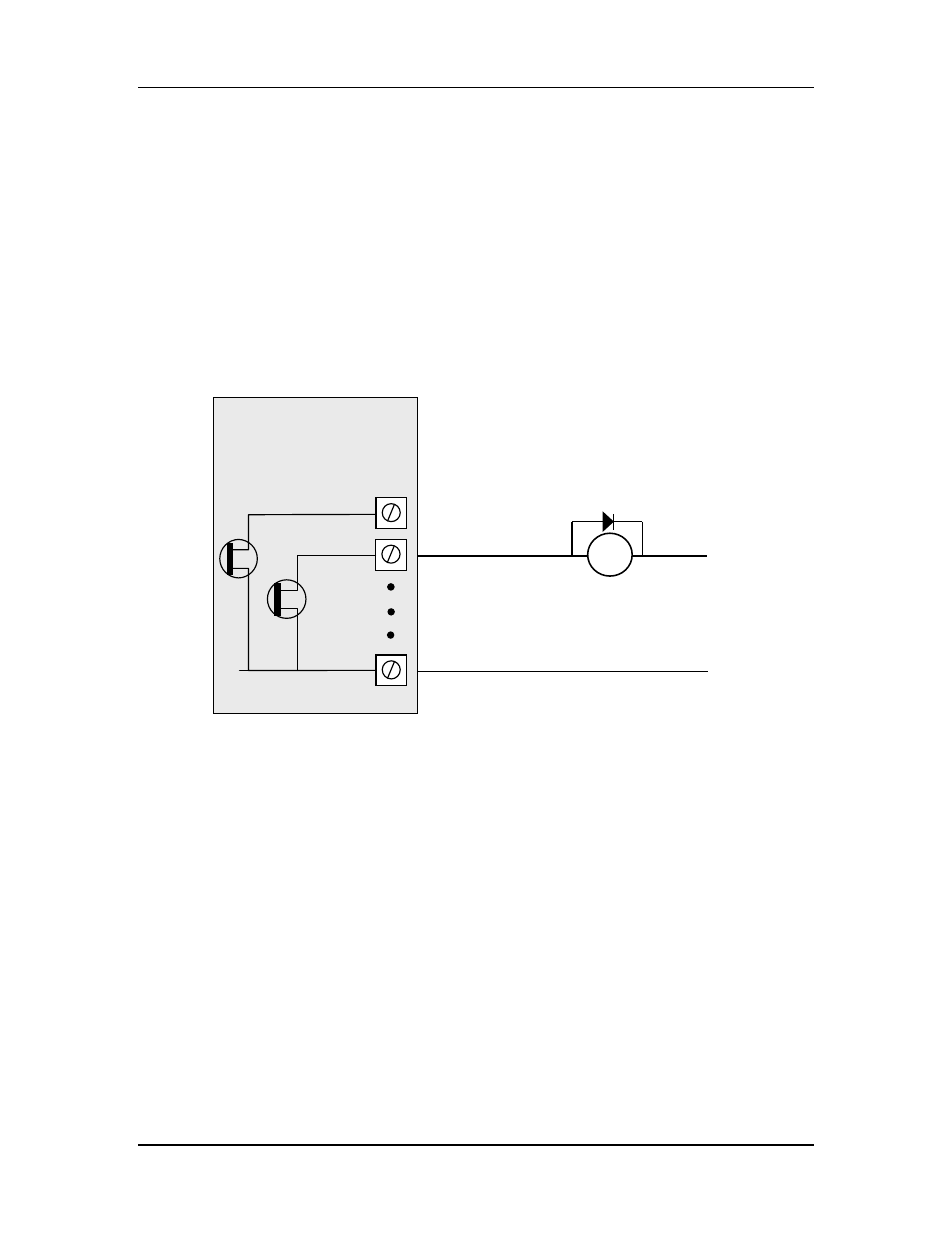
2.2.2 Digital Outputs (and Pulsed Outputs)
The WI-I/O-EX-1-S-11 supports up to 16 digital outputs, shared with the digital input
function on the same terminals. The WI-I/O-EX-1-S-12 and WI-I/O-EX-1-S-13 both
provide 8 digital output signals. These signals are marked DIO1-8, and DIO1-16 for the
WI-I/O-EX-1-S-11. On all WI-I/O-EX modules, DIO1-8 can also operate as pulsed
outputs.
When active, digital outputs provide a transistor switch to EARTH. To connect a digital
output, refer to the diagram in Figure 2-6. A bypass diode is recommended to protect
against switching surges for inductive loads such as relay coils.
Figure 2-6: Connection of digital outputs.
Note that digital outputs will only switch DC circuits, with maximum voltage 30VDC.
2.2.3 Analog Inputs
The WI-I/O-EX-1-S-12 provides eight grounded single-ended or four floating differential
analog inputs. These provide measurement of voltage signals (0-10V) or current (0-20
mA) signals. An internal 24V analog loop supply (ALS) is generated for current loops.
Refer to Section 4.4 for detail on configuring single-ended, differential, current-mode or
voltage mode inputs.
_
+
DC
Load
Max 30VDC
0.2A
V-
DIO1
DIO2
EARTH
WI-I/O-EX Module