Vicor VI Chip Remote Sense PRM Evaluation Board User Manual
Page 3
UG:016
vicorpower.com
Applications Engineering: 800 927.9474
Page 3
Considerations for Remote Sense only PRM
This board is designed to accomodate different types of PRMs. Therefore, certain
circuitry on the board is not populated and there are additional considerations for using
Remote Sense only PRMs.
The Remote Sense PRM Evaluation Board does not operate in default switch S10 setting
which has all switches in the OFF position. Switch at position 1 must remain in the OFF
position. Putting switch at position 1 in the ON position could short the TM pin which
would cause damage. Switch at position 6 must remain in the OFF position as well.
Please see appropriate section for switch setting and mode of operation.
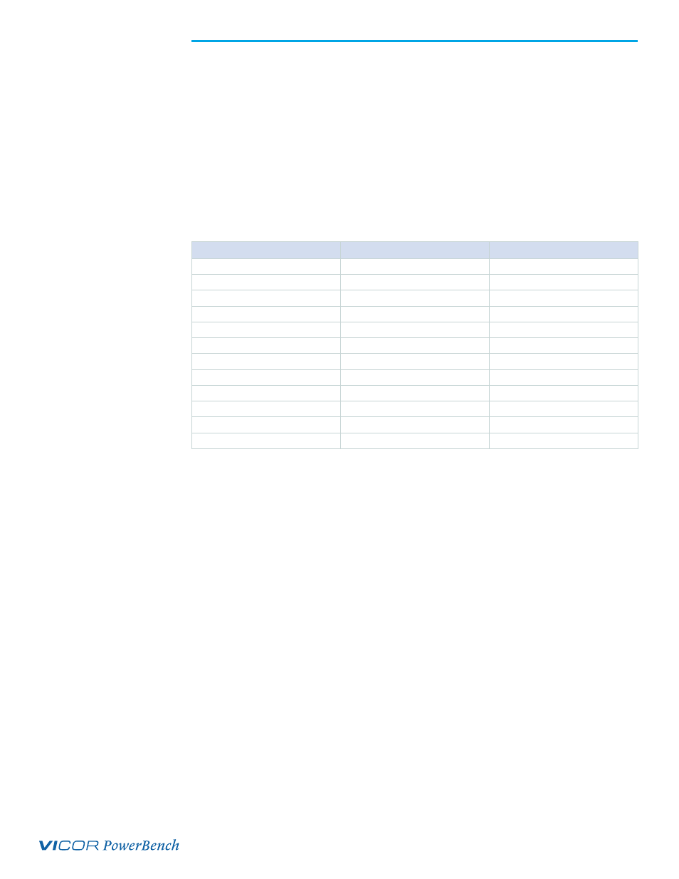
The silkscreen may not match the pin names for Remote Sense PRM. Following table
maps pin names of the Remote Sense PRM to silkscreen and standard PRM.
Remote Sense PRM
PRM
Silkscreen on the Board
PR
SHARE/CONTROL NODE
SH/CN
PC
ENABLE
EN
TM
TRIM
TRIM
NC
NC
TP20
NC
NC
TP19
NC
AL
AL
VC
VC
VC
RE
REF/REF_EN
RE
SG
SGND
SG
IF
IFB
IFB
VS
VAUX
VAUX
NC
VT
VT
Contents
All Remote Sense PRM evaluation boards arrive with the following contents.
(The user guide can be downloaded from the www.vicorpower.com)
n
1 x Remote Sense PRM evaluation board
n
1 x VI Chip push pin heat sink
n
2 x VI Chip push pins for heat sink installation
n
2 x VI Chip push pin heat sink grounding clips
n
1 x hardware kit
n
1 x through-hole aluminum-electrolytic input capacitor (C
IN
)
n
1 x through hole resistor for default compensation (R28)
n
1 x through hole capacitor for default compensation (C20)
n
2 x jumpers
Table 2.