Board operating modes, Line and load connections – Vicor VI Chip Remote Sense PRM Evaluation Board User Manual
Page 19
UG:016
vicorpower.com
Applications Engineering: 800 927.9474
Page 19
Line and Load Connections
n
Make sure that input power supply is OFF.
n
Connect the input power supply positive lead to the +IN input lug of the
evaluation board.
n
Connect the input power supply return lead to the –IN input lug of the
evaluation board.
n
Connect the output lug +OUT to the positive terminal of the electronic load.
n
Connect the output lug –OUT to the return terminal of the electronic load.
n
Verify proper polarity of the connections.
n
Place the input capacitance 22 uF, 100 V.
n
Turn the FAN ON.
n
Have the latest version of the datasheet.
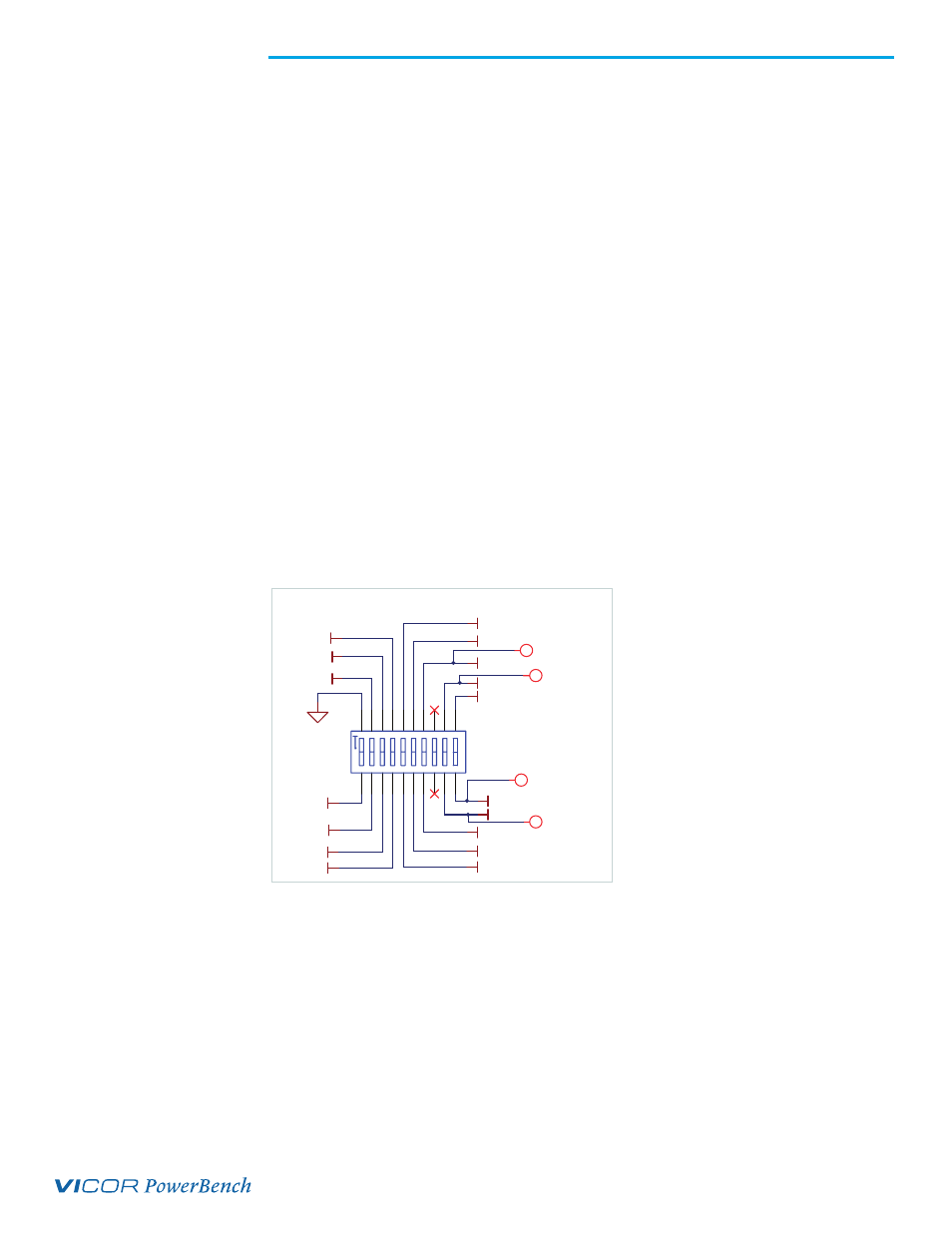
Board Operating Modes
Remote Sense PRM evaluation board supports different Remote Sense configurations.
Therefore, operating mode selection switch S10 is provided on the board for selection of
the following operating modes:
n
Remote Sense: local sensing (single ended)
n
Remote Sense: non-isolated remote sense (differential)
n
Slave (for array operation)
ON
SG
PR
TM
EAO
IF
IMON
LOCAL SENSE_ +
PRM_ +OUT
+SENSE_B
-SENSE_B
+SENSE
-SENSE
RE
VS
VCC
REF_ EN_ B
NC4
V T M_T M
i +S
i -S
i POU T
1 2 3 4 5 6 7 8 9
18 17 16 15 14 13 12 11
10
19
20
S10
SW_ 21910MST
i POU T
Figure 8.
Mode select switch