Remote sense operating mode using prm, Local sensing (single ended), Switch – Vicor VI Chip Remote Sense PRM Evaluation Board User Manual
Page 21: Position on or off connection number, Table 7. switch configuration in local sensing
UG:016
vicorpower.com
Applications Engineering: 800 927.9474
Page 21
Remote Sense Operating Mode using PRM
®
: Local Sensing (Single Ended)
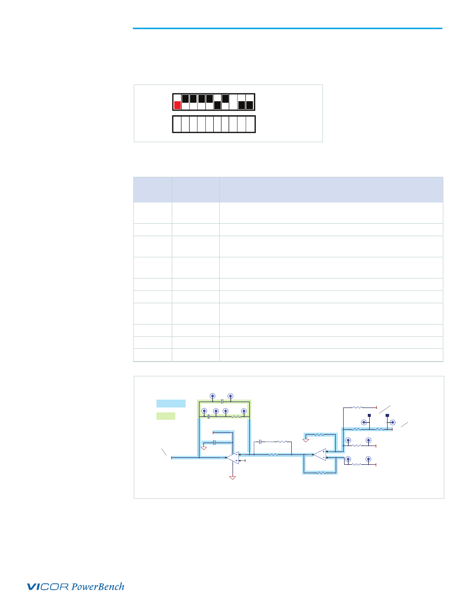
Mode select switch S10 setting: keep the switch S10 setting at all positions as shown in
following illustration.
The following table describes the switch configuration.
In this configuration, PRM operates in Remote Sense. PRM module output voltage is
sensed through divider formed by R29 and R31. U11B is configured as buffer as shown
in Figure 11 and provides the sense voltage to error amplifier U11A. R33, R41 and R27
are left open, reserved for differential sensing and current sensing. R29 is set to limit
the upper trim range based on a maximum reference voltage of 1.25 V. Note that by
default compensation components are not installed and required for operation. Default
compensation components are provided with the board as described in a later section.
LOCAL SENSE (Single Ended)
ON
OFF
1
2
3
4
5
6
7
8
9
10
Postion
number
Switch
Position
ON or OFF
Connection
Number
1 OFF
TM pin must be left open. This switch position cannot be put in the
ON position.
2
ON
PR pin is connected to output of external error amplifier.
3 ON
IF pin is connected to output of external current sense amplifier to set
constant current limit.
4 ON
RE pin is connected to input of the external voltage reference circuit
to generate voltage reference for external error amplifier.
5
ON
VS pin is connected to power VCC of the op-amp and current sense IC.
6
OFF
NC pin must be left open. This switch position cannot be put in the ON position.
7 ON
PRM +OUT pin is connected to local sense (single ended) of the remote
sense control circuitry.
8
Don’t care
9
OFF
See next Remote Sense Operation
10
OFF
See next Remote Sense Operation
Table 7.
Switch configuration
in local sensing
SG
SG
VCC
R32
1206
C22
1206
EAO
R33
1206
SG
R41
1206
+SENSE_B
-SENSE_B
LOCAL SENSE_+
2
3
1
4
8
SO8
U11A
6
5
7
U11B
1206
54.9K
R29
1206
1.27K
R31
1206
1.27K
R42
1206
1K
R36
C21
0603
IMON
R27
1206
H 48
H 47
H 51
H 52
1206
20Ω
R30
H 46
H 45
TP38
TP37
OPEN
OPEN
OPEN
OPEN
OPEN
VREF
To PR through S10
Preinstalled component
and connections
User installed
component
C19
1206
1206
20K
R28
1206
4.7nF
C20
H 39
H 40
H 43
H 44
H 42
H 41
To PRM +OUT
through S10
AC signal
injection
Figure 12.
Remote Sense: local sensing
(single ended) control circuitry
BLUE highlight =
Pre-installed component
GREEN highlight =
user installed component
Figure 11.
Local Sensing
(single ended)