Vicor Mini MegaPAC AC-DC Switcher User Manual
Page 4
UG:110
vicorpower.com
Applications Engineering: 800 927.9474
Page 4
rectifier/voltage doubler configuration. This operates as a full wave bridge rectifier on
230 Vac, or can be manually strapped for operation as a voltage doubler on 115 Vac,
delivering unregulated 300 Vdc to a high voltage backplane. The backplane supplies
power to a variety of ConverterPAC assemblies that provide the desired low voltage,
regulated outputs.
Voltage conversion in the output assemblies is achieved by Vicor's family of
Zero-Current-Switching (ZCS) DC-DC converters. These are forward converters in which
the main switching element switches at zero current. This patented topology has a
number of unique attributes: low switching losses; high frequency operation resulting
in reduced size for magnetics and capacitors; excellent line and load regulation; wide
adjustment range for output; low EMI/RFI emission and high efficiencies.
At initial power-up, the Mini MegaPAC outputs are disabled to limit the inrush current
and to allow the DC bus potential to settle out to the correct operating level. A low-
power flyback converter operating with PWM current-mode control converts the high
voltage DC bus into regulated low voltage to power the internal housekeeping circuits
and DC cooling fan. When operating on 115 Vac, the internal housekeeping Vcc comes
up within two seconds after the application of input power. On 230 Vac, it comes up
within 500 ms. Once the bus potential is within operating parameters, the AC Power OK
signal asserts to a TTL "1" indicating that the input power is OK, and allows the power
outputs to come up within <50 ms later. An auxiliary Vcc output of 5 Vdc sourcing up to
0.3 A is provided for peripheral use on interface connector J10-9.
An output Enable/Disable function is provided by using an optocoupler to control the
Gate In pins of the ConverterPAC assemblies. If the Enable/Disable control pin is pulled
low, the optocoupler turns on, pulling the Gate In pin low and disabling the output.
The typical delay associated for an output to come up when measured from release of
the Enable/Disable pin is 5-10 ms. The General Shutdown function controls all outputs
simultaneously and works in a similar manner.
The ride-through (hold-up) time is the amount of time the load can be supported before
loss of output regulation after the loss of input power. Detecting the loss of input power
takes a finite time period after which the AC Power OK signal goes from a TTL “1” to “0.”
This signal is available for use within 1.2 seconds after initial power-up and can be used
to indicate an impending loss of power. A minimum of 3 ms of warning time is given.
Following the loss of input power, the outputs are disabled when the bus voltage falls
below its operating threshold.
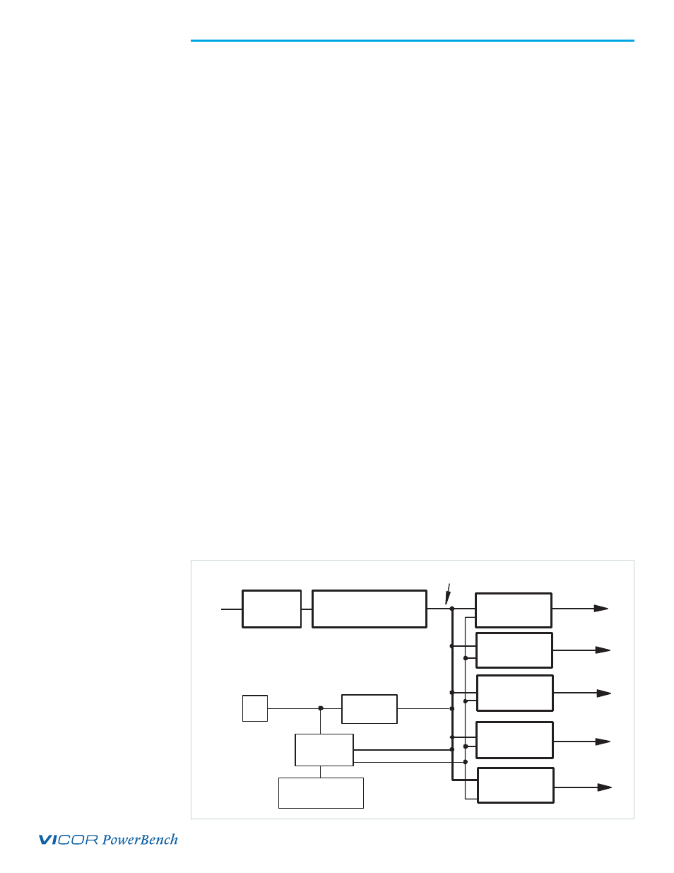
Figure 1.
Mini MegaPAC Architecture
EMI Filter
AC/DC Power Rectification,
Input Voltage Strapping,
Inrush Current Limiting
Logic Power
Supply
Housekeeping
Circuits
DC
Fan
DC Bus Sense
Customer Interface
(Optoisolators)
High Voltage
Unregulated Bus
Power
Input
DC/DC Output
ConverterPAC #1
DC/DC Output
ConverterPAC #2
DC/DC Output
ConverterPAC #3
Power Output
Power Output
Power Output
DC/DC Output
ConverterPAC #5
Power Output
Control
DC/DC Output
ConverterPAC #4
Power Output